Ecolab GEOCENTER Скачать руководство пользователя страница 14

0

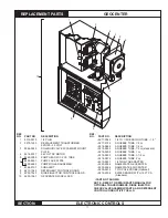
RINSE SPEED CONTROL P.C. BOARD

6.4  Sonalert

®

 Volume adjustment

1.  Turn all alarm delay switches off.
2.  Put the unit into a feed mode by temporarily turning on 

additional titration switches and disrupting detergent feed 

by holding open the Geosystem Detergent Dispenser 

lid.

3.  when the Sonalert

®

 is activated, set the volume using 

the identified potentiometer - clockwise to increase the 

volume,

 refer to Figure 6-1.

The Sonalert

®

 volume should be loud enough to be heard 

over the normal noise levels in the dish room , and yet not 

too loud that it may disturb customers in the dining room.

6.5  Sonalert

®

 alarm Delay

1.  Set the alarm delay by using the 10 position dip switch, 

refer to Figure 6-1. 

SWITCH ON  1  2  3  4  5  6  7  8 

10

SeCONDS 

1  2  4  8  16  32  64  128  256  512

eXAMPLe: For a 2.5 minute (150 second) delay, turn on 

switches #8, #5, #3 and #2.

NOTE: On Door Type Machines, the delay should be 

approximately 30-35 seconds to allow it to be activated 

before the wash cycle is complete.
NOTE: On Conveyer Machines, (unless equipped with 

a  D-ENERGIZER  or  other  time-out  device)  the  delay 

should be a minimum of 2 minutes.

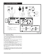
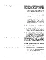
6.6  rinse Speed control

This  is  the  normal  mode  of  operation  as  a  dishmachine 

rinse injector. Thru the pressure switch, the pump is ac-

tivated whenever the final rinse is “on”. By adjusting the 

speed control, the injection rate of the rinse additive can be 

controlled throughout the entire rinse cycle, 

refer to Figure 

6-2.

 Injection rate can also be adjusted by use of alternate 

sized squeeze tubes:

INJECTION RATES


PUMP SPEED

Tube Size 

3 RPM (minimum) 

36  RPM  (maxi

-

mum)

1/8 cc/rev 

3/8 ml (.0125 oz.) 

4.5 ml (.15 oz.)

1/4 cc/rev 

3/4 ml (.025 oz.) 

9 ml (.30 oz.) 

*1/2 cc/rev  1-1/2 ml (.05 oz.) 

18 ml (.61 oz.)

1 cc/rev 

3 ml (.10 oz.) 

36 ml (1.22 oz.)

1-1/2 cc/rev  4-1/2 ml (.15 oz.) 

54 ml (1.83 oz.)

2 cc/rev 

6 ml (.20 oz.) 

72 ml (2.43 oz.)

* Tubing provided with GeoCenter unit.

NOTE: 1cc = 1 ml

Figure 6-2

TIMe/DeLAY

POTENTIOMETERS

PuMP SPEED

POTENTIOMETER

NOTE: The best injection rates are achieved in the 10-20 

revolution per minute range. It is recommended to select 

the tubing that allows mid range operation.

6.7  Timed feed

In this mode of operation, the dispenser will activate for a 

pre-set period of time. This would be used when dispensing 

control is determined by volume, 

refer to Figure 6-2.

Note  that  the  TIME  FEED  and  the  SPEED  CONTROL 

modes can be used together. For example, if the injector 

is activated during the fill cycle on a door type machine, by 

setting the TIME FEED for just a few seconds longer than 

the normal rinse time, this will be the maximum length of 

time the product will be injected during the fill.

6.8  feed Delay

This feature can be used with either the SPEED CONTROL 

or TIME FEED mode. This is adjustable from 0 to 10 seconds, 

and delays the pump activation for that period of time after 

the unit is activated, 

refer to Figure 6-2.

Содержание GEOCENTER

Страница 1: ...GEOCENTER Installation and Operation Manual Dispenser Complete 9223 1091 26392 0406 0409 Copyright Ecolab Inc 2009 9223 2610...

Страница 2: ...This page intended to be blank...

Страница 3: ...lation 5 4 6 VANGUARD Wash Max Installation 5 4 7 Geosystem Rinse Dispenser 6 4 8 Rinse Injector Connections 6 4 9 Hydraulic Connections and Visual Flow Indicator 6 5 0 ELECTRICAL CONNECTIONS 7 5 1 Tr...

Страница 4: ...13 9 3 Unit does not feed Power Light on Feed Light not on 14 9 4 Feeds continuously Feed Light not on 14 9 5 Feeds continuously Feed Light on 14 9 6 Fluctuating titration 15 9 7 Excessive detergent c...

Страница 5: ...ines will be suggested in reference to the preferred method of installation however the variety of equipment and the surrounding physical environment will dictate the actual installation of the GeoCen...

Страница 6: ...ergent when wash tank concentration is near the desired control point Visual indicators signal concentration status of the wash tank A FEED light will illuminate when concentration is below the set le...

Страница 7: ...a 440 volt installation IMPORTANT Make sure the power source is turned off 3 1 Dimensions Height H 7 5 8 19 4 cm Width W 11 3 8 28 9 cm Depth D 6 3 8 16 2 cm Weight 12 LB 5 4 kg 3 2 Access Requiremen...

Страница 8: ...inimum 14 GA 600 volt insulated wire Wiring from the power source to the transformer must be enclosed in conduit seal tite or other housing approved for damp locations 3 5 Plumbing Requirements Water...

Страница 9: ...er to Figure 4 1 Attach to plastic GeoCenter enclosure with 8 32 x 5 16 screw in kit bag Ground using green yellow wire 4 3 Mounting the GeoCenter 1 Mount the GeoCenter cabinet to the wall using the s...

Страница 10: ...ID PVC tubing provided 3 Insert this injection tubing assembly fully into the outlet end of the Flow Indicator tube also called the sight tube 4 Secure all connections with the clamps provided 5 Comp...

Страница 11: ...SOLID RINSE RESERVOIR RED BLACK GREEN WHITE HI S26 ON 10 11 12 13 14 15 16 17 18 19 20 21 22 23 OFF FEED ALARM VOLUME ALARM DELAY TITRATION ALARM 100 POWER LED LED JP2 FEED OFF FEED ADJUST 5 0 ELECTR...

Страница 12: ...ductor cable between the GeoCenter and Detergent units At the GeoCenter Refer to Figure 5 1 on page 7 Wire nut the leads from the 2 conductor cable to the two WHITE wires provided with the wire nuts 5...

Страница 13: ...8 16 32 64 APPROX STANDARD DROPS 1 2 4 8 16 32 When multiple positions are ON the detergent controller will add all positions together to achieve the desired tank concentration Example using Standard...

Страница 14: ...ntrol the injection rate of the rinse additive can be controlled throughout the entire rinse cycle refer to Figure 6 2 Injection rate can also be adjusted by use of alternate sized squeeze tubes INJEC...

Страница 15: ...limitations in sensor technology the thermistor in the S 2000 sensor responds slowly to changes in wash tank temperature Under certain conditions this slow response can cause the detergent controller...

Страница 16: ...away from pump body until tubes slips over the rollers 4 Clean inside of pump body wiping to remove particle matter and accumulation of old lubricant 5 Inspect the roller assembly closely for signs o...

Страница 17: ...at valve coil if present a Check for water to the valve b Disconnect the outlet tubing from the valve If water flowsthruthevalve checkforplugorrestrictionintubing to the reservoir or in the reservoir...

Страница 18: ...lly increasing If not there is no detergent being delivered to the machine or the detergent is not feeding into the wash tank Check for proper water flow to the dispenser properoperationofthedispenser...

Страница 19: ...wn wire from terminal 15 and readjust the titration according to section 7 4 If titrations stabilize use this setting for operation 3 Check for signs of moisture contamination on the de tergent contro...

Страница 20: ...air leaks 2 Check for high rinse pressure optimum is 15 20 psig 1 1 4 BAR and cannot be over 35 psig 2 4 BAR 3 Check squeeze tube for wear and cracks etc 1 Lubricate use only silicon grease lubricate...

Страница 21: ...ER W CELL PKD INJECTOR CONTROL BOARD 9217 0042 1 4 TO 1 8 REDUCING TUBE 1 5 9218 0884 SQUEEZE TUBE 1 4 cc 9217 0125 SQUEEZE TUBE 1 8 cc standard 9218 0892 SQUEEZE TUBE 1 2 cc 9218 0900 SQUEEZE TUBE 1...

Страница 22: ...nse injector On these machines a constant power source L1 L2 is applied to the injector transformer and a rinse pressure switch will have to be installed The rinse injector will then be activated when...

Отзывы: