13
www.ecoflam-burners.com
EN
420010813300
INSTALLATION
Electrical connections
!
WARNING:
Electrical wiring must be carried out with electrical supply disconnected and with burner switch in position OFF.
Electrical supply must correspond to the one shown on the burner label.
APPLICABLE STANDARD
The electrical connection work comprising
all the installation materials, terminals and
earth connections must be carried out in
accordance with the applicable
regulations. For the electrical installation of
the burner care must be taken to observe
the circuit diagram made out for the
furnace system.
The electrical connection of the burner and
instruments shall be entrusted to
authorized specialists only.
NOTE:
For the installation of the
connection cables care must be taken to
provide cable loops of sufficient length to
allow for the swing-out of the boiler door
and burner.
Make sure after the completion of the
electrical connection work to check the
wiring of the electrical system of the
burner. This should include a check of the
direction of rotation of the burner motor
(fan).
GENERAL WARNINGS:
All applicable electrical safety regulations
must be followed. Failure to correctly
dimension the suitable input power and
earth the equipment may cause damages
to person and compromise the correct
function of the burner therefore the
electrical system shall be checked by
qualifed personnel.
The manufacturer declines all
responsibility for modifcations or
connections different from those shown in
the electrical scheme.
Adapters, multiple plugs and extension
cables may not be used for the
equipment’s power supply.
An omnipolar switch in accordance with
current safety regulations is required for
the mains supply connection.
ELECTRICAL CONNECTION
1) of the burner
- Built-in electrical cabinet
Use cable gland in order to secure the
required level of protection. All the links,
power and control, are connected to the
terminal block of the cabinet. Provide
cables in sufficient length to secure the
rotation of the burner body according to
the assembly.
Check and adjust the size of the
contactors and thermal relays and the
wires section according to the motor and
supply voltage specs.
ATTENTION:
Wiring is not supplied.
The burners are produced with
connections suitable for power supply
380-400 V three-phase.
The burners with electric motors of an
output lower or equal to 3 kW can be
adapted to 220-230 V (please follow the
instructions on the backside); motors with
higher output can only work 380-400 V
three-phase. In case of request of burners
different from the above mentioned
standard, it is recommended to make
specific mention in the order.
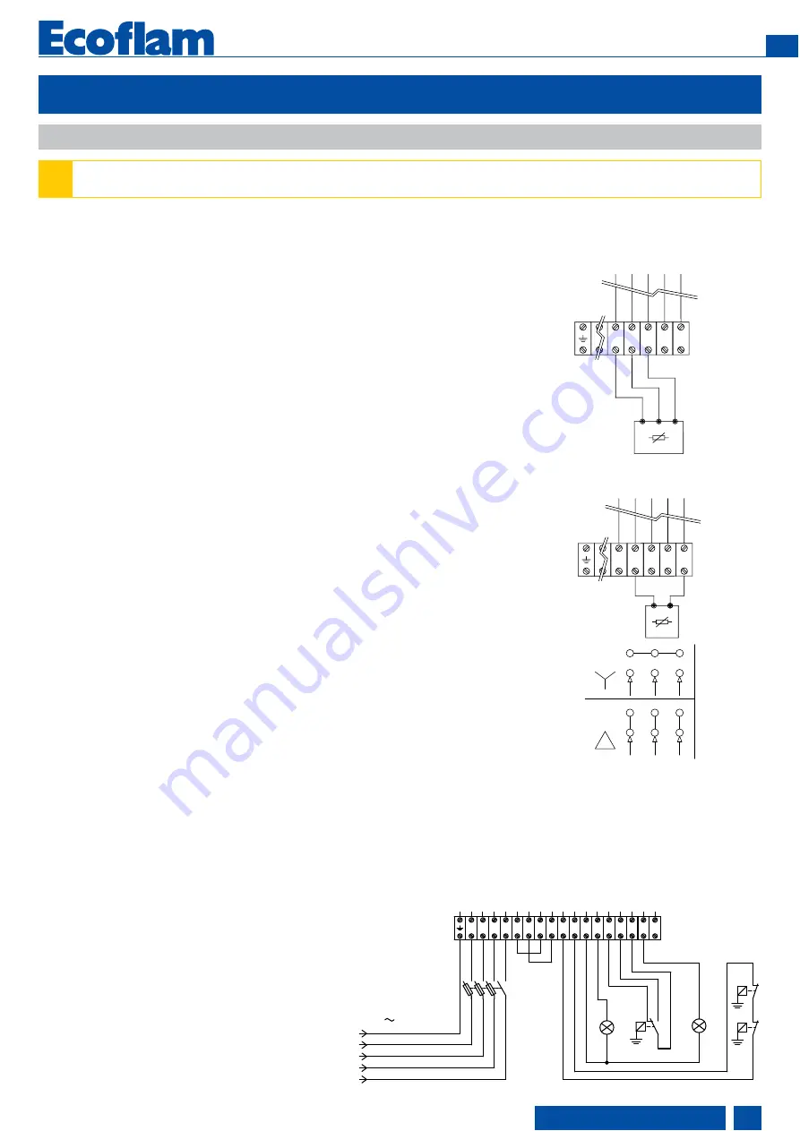
Instructions: how to adapt electric
motors of an output lower or equal to 3
kW to 220-230 V power supply
It is possible to change the voltage of the
burner by operating as follows:
1. change the connection inside the
electric box of the motor, from star to delta
(see picture 1);
2. change the setting of the thermal relay,
referring to the absorption values indicated
in the motor nameplate. If necessary,
replace the thermal relay with another one
of suitable scale.This operation is not
possible on motors above 3 kW.
For more information, please contact the
Ecoflam staff.
LEGENDA
HLB: lock-out lamp
STAB: two stages thermostat
HLF: burner on flame lamp
STC: boiler thermostat
STS: safety thermostat
SA: active probe
SP: passive probe
T
P
P
T
P
T
STAB
9
Q
N
R
S
T
7
6
5
8
S
N
T
R
PE
50 Hz 400V
13
12
11
10
4
1
2
3
STC
HLB
STS
HLF
PROBES CONNECTION
9
13
12
11
10
SA
Q
BE
....
G
L
M
U1
ACTIVE PROBE CONNECTION
(FOR MODULATING VERSION)
12
13
11
9
10
S
P
Q
AE
...
M
B
PASSIVE PROBE CONNECTION
(FOR MODULATING VERSION)
230V
400V
fig.1
Содержание MAIOR P 500-1 PRE
Страница 31: ...31 www ecoflam burners com EN 420010813300...


