background image


32 


Two: sensor and its related faults 

1.  Overview of faults 
Short-circuit and open circuit of the temperature sensing bag, all of which have fault code display. 
Indoor: environmental sensor failure, pipe temperature sensor failure. 
Outdoor: the environmental sensor, outdoor pipe temperature sensor and exhaust temperature sensor are faulty. 
Sensor resistance is abnormal 
If the sensor resistance is abnormal or the sensor with wrong specification is replaced during maintenance, the fault code of the 
sensor is generally not displayed, but it may cause abnormal protection frequency limiting, abnormal protection shutdown and other 
related codes to be displayed. Faults caused by abnormal sensor resistance are invisible and complicated to deal with. Whether the 
sensor resistance is normal or not can be rechecked in case of abnormal phenomena. 
2. Cause 

of 

failure 

When the sensor is open or short-circuited, the detection circuit voltage is close to the power supply voltage or 0V. The power 
supply voltage of outdoor unit is 3.3V or 5V, and that of indoor unit is 5V. 

3.    Possible failure point 

Poor contact and looseness of sensor terminal 
Sensor circuit components loose, open circuit, virtual welding 
Sensor resistance offset 
Sensor circuit resistance offset, capacitor leakage 
The sensor specification is wrong, for example, 10K is used as 50K 
Abnormal controller chip 
The sensor bulb is short-circuited with the shell or copper pipe 


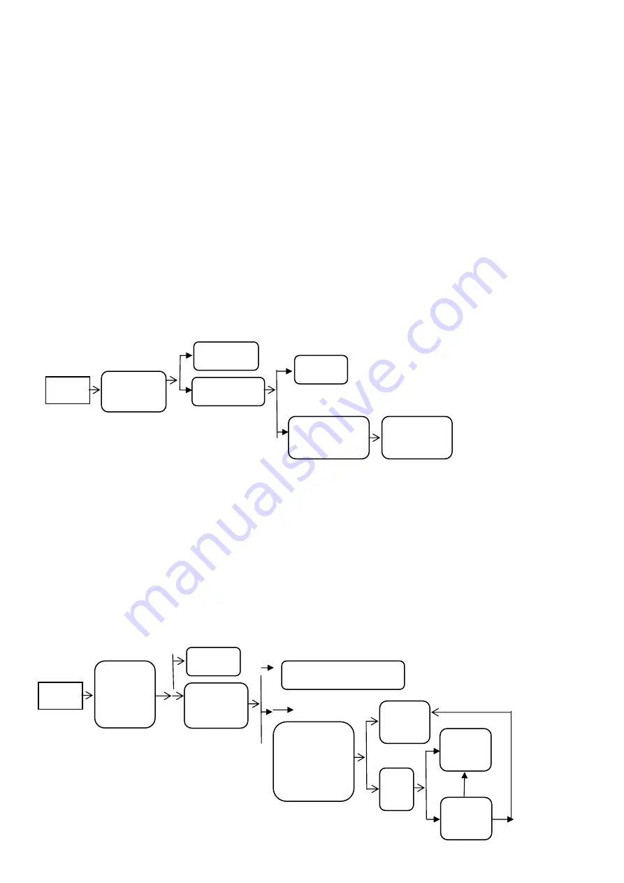
4. Fault handling flow 


Three: indoor fan failure 


1.  Overview of faults 
"F0" is displayed indoors, and F0 fault is mainly to prevent abnormal rotating speed from turning into fault of electronic control and 
refrigerant circulation system. 
2. Cause 

of 

failure 

When the fan is turned on, the indoor main chip detects that the motor speed is lower than 300 rpm for 1 minute continuously 
(through the fan feedback circuit), and the controller reports the fault of the internal fan. 
3. Possible 

failure 

point 

Whether the motor is installed correctly, whether the terminals are plugged firmly, whether the blades are stuck, whether the 
eccentric tuyere of the sliding bearing in the rubber ring is blocked and the wind speed is too slow. 
Fan starting capacitor is damaged 
The internal controller is abnormal 
The motor body is stuck and damaged (peculiar smell, open or short circuit of windings are abnormal. When measuring the winding 
resistance, pay attention to distinguish whether the thermal protector acts due to the high temperature of the motor casing). Note: If 
there is an "FO" fault in case of uncertainty, please check the fan blades and motor equipment and add proper lubricating oil. 
4. Fault 

handling 

flow 


NO


YES


Sensor 
failure


Is the terminal plug 
loose or poor 
contact 

Reconnect and plug 
in the terminals 

Is the sensor resistance 
normal 

Replace sensor 

Is the sensor lead broken 
or short-circuited by other 
devices or copper pipes 

Replace the sensor 
and readjust the 
sensor routing 

NO


NO


YE
S


YE
S


NO


YE
S


Internal fan 
failure


Whether the 
contact between 
motor control 
output and 
feedback end is 
firm 

Reinsert the 
terminals 

Turn the blades by 
hand to see if they 
rotate smoothly 

Re-assemble blades, motors and sliding 
bearings correctly 

Measure whether the 
output voltage at the 
control end of PG motor 
is greater than 50V 
within one minute after 
being powered on again 
and the air deflector is 
turned on. 

Replace the 
main 
controller of 
the same 
model

Motor 
startin

Test whether 
there is 
feedback 
signal 

Replace the 
internal 
board 

NO


NO


NO


YE
S


YE
S


YE
S


NO


Содержание CM2-H16/4DR2

Страница 1: ...Service manual FREE MATCH 50Hz R32 Models СM2 H16 4DR2 СM3 H22 4DR2 2022 06 ...

Страница 2: ...ystem Diagram 10 6 Schematic Diagram 10 6 1 Electrical Wiring 10 7 Installation Manual 12 7 1 Standard Accessory Parts 12 7 2 Safety operation of flammable refrigerant 13 7 3 Installation Location and Matters Needing Attention 15 7 4 Test operation 23 8 Exploded Views and Parts List 24 8 1 Outdoor Unit 24 9 Troubleshooting 28 9 1 PCB Printed Diagram 28 10 Removal Procedure 30 10 1 Removal Procedur...

Страница 3: ...1 1 Summary and Features Outdoor Unit CM2H 1644A23 CM3H 2228A23 ...

Страница 4: ...the air shall in no way exceed its limited value or it may lead to explosion Keep your fingers and clothing away from any moving parts Clear the site after installation Make sure no foreign objects are left in the unit Always ensure effective grounding for the unit Warning Caution All electric work must be performed by a licensed technician according to local regulations and the instructions given...

Страница 5: ... nonpolluting refrigerant with no harm to the ozonosphere The influence upon the greenhouse effect is also lower R32 has got very good thermodynamic features which leads to a really high energy efficiency The units therefore need a less filling WARNING Do not use means to accelerate the defrosting process or to clean other than those recommended by the manufacture Should repair be necessary contac...

Страница 6: ... Energy Class A A A A Air Flow Volume 2800 3100 Air Flow Volume m3 h 1647 1824 Sound Pressure Level CFM 54 56 Sound Power Level dB A 64 66 Rated Voltage dB A 220 240 220 240 Rated Frequency V 50 50 Phases Hz 1 1 Min Max Voltage 165 264 165 264 Cross sectional Area of Power Cable Conductor V 1 50 2 50 Cross sectional Area of Power Cable Conductor mm2 0 0023 0 0039 Recommended Power Cable Core sq in...

Страница 7: ...ber of Rows 2 2 Condenser Tube Pitch a Row Pitch b mm 22 19 05 22 19 05 Condenser Fin Pitch mm 1 4 1 4 Condenser Fins per Inch FPI 18 18 Condenser Fin Type wavy fin wavy fin Condenser Fin Colour GOLDEN GOLDEN Condenser Number of Circuits 4in 4out 6in 3out Condenser Length L Height H Width W mm 854 594 38 1 914 660 38 1 Condenser Max Allowable Pressure MPa 12 6 12 6 Outdoor max operating pressure o...

Страница 8: ... 12 Outer Diameter of Liquid Pipe Metric 1 mm φ6 φ6 Outer Diameter of Liquid Pipe Metric 2 mm φ6 φ6 Outer Diameter of Liquid Pipe Metric 3 mm φ6 Outer Diameter of Liquid Pipe Metric 4 mm Outer Diameter of Liquid Pipe Metric 5 mm Outer Diameter of Gas Pipe Metric 1 mm φ9 52 φ9 52 Outer Diameter of Gas Pipe Metric 2 mm φ9 52 φ9 52 Outer Diameter of Gas Pipe Metric 3 mm φ9 52 Outer Diameter of Gas Pi...

Страница 9: ... 110 100 90 80 70 60 50 40 Heating 32 33 34 35 36 37 38 39 40 41 42 43 44 45 46 Outdoor temp C Heating operation ambient temperature range is 15ºC 24ºC Cooling 130 120 110 100 90 80 70 60 20 15 10 5 0 5 10 Outdoor temp C Heating 110 100 90 80 70 60 50 50 32 33 34 35 36 37 38 39 40 41 42 43 44 45 46 40 15 10 5 0 5 7 10 Outdoor temp C Outdoor temp C Current A Current A Condition Indoor DB 20 C Indoo...

Страница 10: ...8 22K 16K 3 4 Noise Curve Outdoor side noise when blowing 62 60 58 56 54 52 50 48 46 20 30 40 50 60 70 80 90 Compressor frequency Hz Noise dB A ...

Страница 11: ...9 4 Construction Views 4 1 Outdoor Unit CM2H 1644A23 Unit mm ...

Страница 12: ...10 CM3H 2228A23 Unit mm ...

Страница 13: ...go the main valve After that it will be divided and go to the heat exchanger of each indoor unit to exchange heat with the air which needs to be conditioned Consequently the refrigerant liquid become low temperature low pressure refrigerant gas again Such a refrigerant cycle goes round and round to achieve the desired cooling purpose During the heating operation the four way valve is involved to m...

Страница 14: ...12 CM2H 1644A23 CM3H 2228A23 These circuit diagrams are subject to change without notice please refer to the one supplied with the unit ...

Страница 15: ... and should be used as required Table 1 Joined with the connection pipe connected with indoor Unit Joined with the pipe joint of outdoor Unit Pipe Joint Subassembly Table 1 NO Joined with the connection pipe connected with indoor Unit Joined with the pipe joint of outdoor Unit Usage 1 Φ12 7 Φ9 52 one for 18K unit 90 ...

Страница 16: ... the requirement of the nameplate It s only allowed to be operated in the rooms that meet the requirement of the nameplate Check whether the maintenance area is well ventilated The continuous ventilation status should be kept during the operation process Check whether there is fire source or potential fire source in the maintenance area The naked flame is prohibited in the maintenance area and the...

Страница 17: ... wire is not long enough please contact a local service center authorized and ask for a proper electric wire Poor connections may lead to electric shock or fire 8 Use the specified types of wires for electrical connections between the indoor and outdoor units Firmly clamp the wires so that their terminals receive no external stresses Electric wires with insufficient capacity wrong wire connections...

Страница 18: ...bient temperature is lower than 0 C 32 F Besides the installation of the outdoor unit should not affect the heat radiation of the unit CAUTION The unit installed in the following places is likely to run abnormally If unavoidable please contact the professional personnel at the appointed service center Where is full of oil Alkaline soil off the sea Where there is sulfur gas like sulfur hot spring W...

Страница 19: ... not affect neighbors or surroundings 4 Do not stack obstacles near the air outlet of the outdoor unit otherwise it would reduce the working capability of the unit or increase the working noise 5 In the event of the occurrence of abnormal noise please contact the sales agent as soon as possible 6 Accessories for installation Refer to the packing list for the accessories of the indoor and outdoor u...

Страница 20: ...y Code of the Indoor and Outdoor Units Table 4 Energy Level Capacity Code Indoor Unit 09 26 12 35 18 52 Outdoor Unit 16 47 22 64 1 The outdoor unit with energy level 16 can drive up to two sets of indoor units the outdoor unit 22 can drive up to three 2 The sum of the capacity codes of the indoor units should be among 50 150 of that of the outdoor unit Wiring of the Power Cord CAUTION A breaker mu...

Страница 21: ...frigerant Pipe Table 5 Allowable Length Refrigerant Pipe 16K 22K 16K 22K Totlal Length m 45 65 L1 L2 L1 L2 L3 Max Length for Single Unit m 25 25 LX Max installation altitude Outdoor unit and indoor unit 10 10 H1 Indoor unit and indoor unit 5 5 H2 ...

Страница 22: ...s of the indoor unit by force otherwise the capillary pipe or other pipe may crack which then would result in leakage 2 The refrigerant pipe should be supported by brackets that is don t let the unit withstand the weight of it CAUTION For the MULTI S inverter air conditioner unit each pipe should be labeled to tell which system it belongs to avoid mistaken inaccurate piping Installation of the Pro...

Страница 23: ...alve vacuum pump Fig 5 Calculation of the Additional Refrigerant Charging 1 Refrigerant Charge in the Outdoor Unit before Shipment Table 8 Model Refrigerant Charge kg CM2H 1644A23 1 10 CM3H 2228A23 1 42 Notes 1 The refrigerant charge mentioned in the table above is not include those charged additionally in the indoor unit and the refrigerant pipe 2 The amount of the additional refrigerant charge i...

Страница 24: ...ngth of each liquid refrigerant pipe is a b c 20 15 15 50m Thus the minimum additional refrigerant charge 50 15 0 012 0 42kg Note no additional refrigerant is needed for the liquid pipe within 15m 4 Additional Refrigerant Charge Record Table 12 Indoor Unit No Indoor Unit Model Additional Refrigerant Refrigerant kg 1 2 3 N Total Table 13 Refrigerant Pipe Diameter Total Length m Additional Refrigera...

Страница 25: ...be burnt out Is there any obstacle at the air inlet outlet of theindoor outdoor unit The cooling heating capacity may be poor Have the length of the refrigerant pipe and the refrigerant charge been recorded It may be hard to know the exact refrigerant charge Trial Running 1 Check before the Trial Running 1 Check if the appearance of the unit and the piping system are damaged during the transportat...

Страница 26: ...ir conditioner to the client 2 Method of test operation Put through the power press ON OFF button on the remote controller to start operation Press MODE button to select AUTO COOL DRY FAN and HEAT to check whether the operation is normal or not If the ambient temperature is lower than 16 the air conditioner can t start cooling ...

Страница 27: ...25 8 Exploded Views and Parts List 8 1 Outdoor Unit Model CM2H 1644A23 ...

Страница 28: ...or 810974791 1 12 EEV coil 811064402 1 13 Valve mounting plate 811127703 1 14 cut off valve 3 8 810638811 2 cut off valve 1 4 810638805 2 15 Lateral plate assembly 811127711 1 16 Valve cover 811127693 1 17 electric cover subassembly 811150205 1 18 Decorative cover 811127692 2 19 Electronic expansion valve assembly 811155562 1 20 Suction pipe 811109151 1 21 four way valve subassembly 811134078 1 22...

Страница 29: ...27 Model CM3H 2228A23 ...

Страница 30: ... cut off valve 3 8 810638811 3 cut off valve 1 4 810638805 3 14 Lateral plate assembly 811127709 1 15 Valve cover 811127693 1 16 electric cover subassembly 811150205 1 17 four way valve subassembly 811121253 1 18 Suction pipe 811121249 1 19 3 8 Connecting pipe 811121233 1 20 3 8 Connecting pipe 811121232 2 21 Electronic expansion valve assembly 811121262 1 22 EEV coil 811064402 3 23 5 8 Connecting...

Страница 31: ...emp sensor 7 EEV B Electronic expansion valve Connect No B system electronic expansion 8 EEV A Electronic expansion valve Connect No A system electronic expansion 9 EEV C Electronic expansion valve Connect No C system electronic expansion 10 EEV D Electronic expansion valve Connect No D system electronic expansion 11 DC FAN Fan interface Connect outdoor fan interface 12 4V 4 way valve interface Co...

Страница 32: ...ing internal disk protection P9 23 IPM protection shutdown F9 24 IPM module failure P2 25 Outdoor AC current protection shutdown P6 26 Overheat protection of refrigeration outer coil P4 Overheat protection of inner coil unit P1 27 Exhaust Temperature Overheat Protection Shutdown E0 28 Compressor shell top failure protection E6 31 Conflict Failure of Indoor Machine Mode L1 33 Drive bus under voltag...

Страница 33: ...ting wires of internal and external machines damaged aged misconnected and the resistance between wires decreases below mω Replace the connecting lines of internal and external machines Generally communication failures after a period of operation are caused by connecting lines Take off the connecting wires of internal and external machines and test whether the impedance of each wire is correct by ...

Страница 34: ...t circulation system 2 Cause of failure When the fan is turned on the indoor main chip detects that the motor speed is lower than 300 rpm for 1 minute continuously through the fan feedback circuit and the controller reports the fault of the internal fan 3 Possible failure point Whether the motor is installed correctly whether the terminals are plugged firmly whether the blades are stuck whether th...

Страница 35: ...external DC fan is abnormal which is caused by poor contact of fan wires damage of fan or damage of electronic control components 3 Possible failure point Unstable connection of DC motor The coil of DC fan is burnt out The fan blade is stuck by foreign matter Outdoor controller failure 4 Fault handling flow VI Over current protection fault 1 Overview of faults The indoor unit shows overcurrent pro...

Страница 36: ...the indoor evaporator is dirty and blocked the fan motor is faulty and the internal air deflector is not turned on Compressor phase current protection process reference module overcurrent protection 4 Fault handling flow Seven capacitor charging fault 1 Overview of faults The voltage charging fault EA is displayed indoors The fault protection of capacitor charging circuit is mainly to ensure the n...

Страница 37: ...embly 2 Remove top cover Remove connection screws connecting the top cover plate with the front panel and the right side plate and then remove the toppanel 3 Remove grille and panel A Remove connection screws between the front grille and the front panel Then remove the front grille B Remove connection screws connecting the front panel with the chassis and the motor support and then remove the fron...

Страница 38: ...insert of the motor Then remove the motor 5 Remove big handle valve cover Remove the connection screw fixing the big handle and then remove the handle Use a screwdriver to fixed valve cover screwdrive pull up to remove the valve cover 6 Remove right side plate Remove connection screws connecting the right side plate with the valve support and the electric box Then remove the right side plate ...

Страница 39: ... wire bundle and unplug the wiring terminals Then lift the electric box to remove it 8 Remove motor support Unscrewed the chassis and the motor bracket fixed screw motor bracket is desirable 9 Remove acoustic cotton Split the acoustic cotton lock and take out 3 pcs slowly NOTE Do not damage the pipe ...

Страница 40: ...d damage to thevalve caused by high temperature When unsoldering the spot weld wrap the 4 way valve with wet cloth completely to avoid damaging the valve due to high temperature 11 Gas liquid separator and diaphragm Open the suction of spot welding remove the suction pipe Use a screwdriver unscrewed the fixed screw of gas liquid separator the upward gas liquid separator remove the gas liquid separ...

Страница 41: ...d valve and condenser and then remove the expansion valve assy 13 Remove the compressor A Remove the 2 screws fixing the gas valve and unsolder the welding joint between the gas valve and the air return pipe to remove the gas valve B Remove the foot nuts on the compressor and then remove the compressor ...

Страница 42: ...ove top cover Remove connection screws connecting the top cover plate with the front panel and the right side plate and then remove the toppanel 3 Remove grille and panel A Remove connection screws between the front grille and the front panel Then remove the front grille B Remove connection screws connecting the front panel with the chassis and the motor support and then remove the front panel ...

Страница 43: ...insert of the motor Then remove the motor 5 Remove big handle valve cover Remove the connection screw fixing the big handle and then remove the handle Use a screwdriver to fixed valve cover screwdrive pull up to remove the valve cover 6 Remove right side plate Remove connection screws connecting the right side plate with the valve support and the electric box Then remove the right side plate ...

Страница 44: ...inals Then lift the electric box to remove it 8 Remove motor support and reinforcing plate Unscrewed the chassis and the motor bracket fixed screw motor bracket is desirable Remove the reinforcement plate by unscrewing the screws 9 Remove acoustic cotton Split the acoustic cotton lock and take out 3 pcs slowly NOTE Do not damage the pipe ...

Страница 45: ...d damage to thevalve caused by high temperature When unsoldering the spot weld wrap the 4 way valve with wet cloth completely to avoid damaging the valve due to high temperature 11 Gas liquid separator and diaphragm Open the suction of spot welding remove the suction pipe Use a screwdriver unscrewed the fixed screw of gas liquid separator the upward gas liquid separator remove the gas liquid separ...

Страница 46: ...alve support Screwdriver unscrew the valve and valve bracket set screw remove the air valve subassembly and hydraulic valve open air valve subassembly of spot welding take down the various valve Screwdriver unscrew the valve bracket and the chassis of the fixed screw take down the valve support 14 Remove Compressor Remove the foot nuts on the compressor and then remove the compressor ...

Страница 47: ...41 ...

Отзывы: