11
BrightFire 200, V1, Operating Instructions, Edition 09.15
Adjustment, Start
and Stop
BrightFire 200 Flame Adjustments
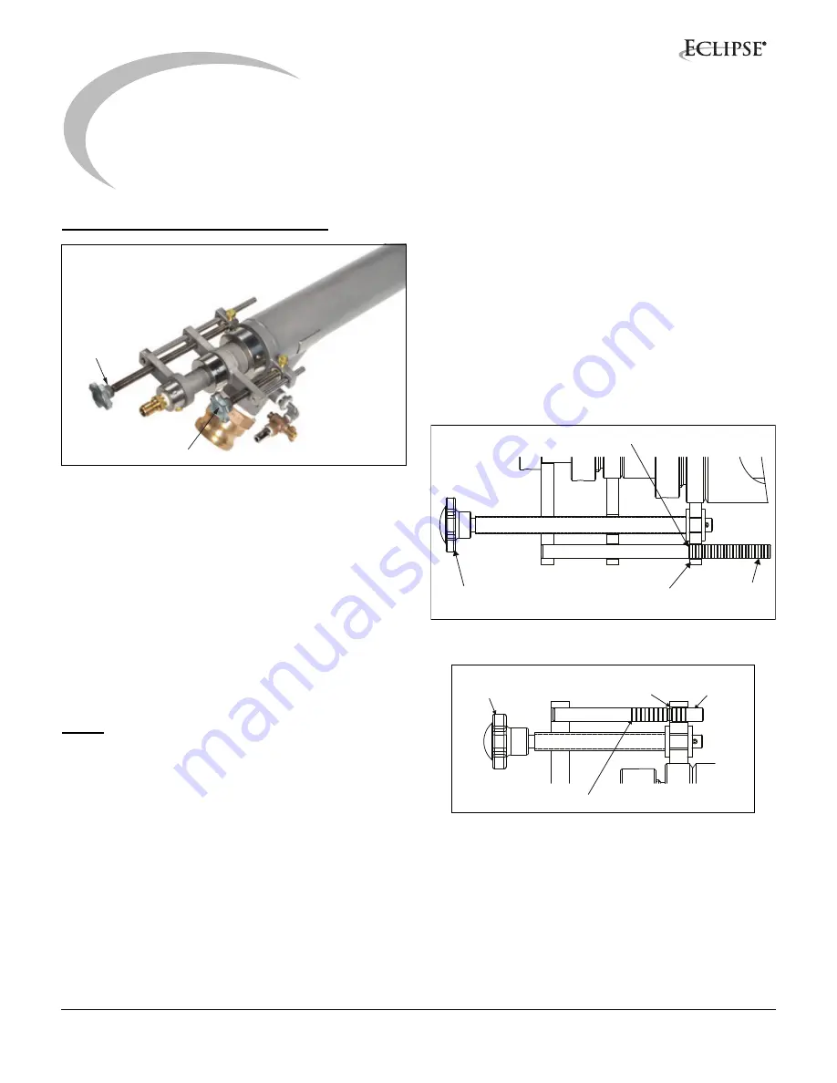
Figure 2.1. BrightFire 200 Adjustments
The BrightFire
®
200 has two adjustment valves, an area
adjustment (see Figure 2.1) and a flow adjustment. The
area adjustment (see Figure 2.2) changes the annulus
area between the inner and outer nozzles and is used to
control flame length. The flow adjustment (see Figure 2.3)
opens and closes an internal valve that changes the
distribution of gas flow between the outer and inner gas
tubes and is used to control where the heat from the flame
is released in the furnace. This can be changed
independently of the flame length. In addition, the firing
angle of the burner can be adjusted using the gimbal
mounting bracket adjustments to optimize gas flow into
the air stream. (Refer to Gimbal Bracket Info Guide 1113.)
NOTE:
Mounting bracket adjustments should only be
done on the off-firing side to prevent natural gas from
deflecting back into the port area if the seal between the
socket plate and burner nozzle is lost.
To adjust the burners once the furnace is at, or near,
normal operating conditions, begin by adjusting the area
adjustment to set the flame to the desired length.
Increasing the annulus area by moving the adjustment
back (counter-clockwise rotation of the adjustment knob)
will lengthen the flame while moving the adjustment
forward (clockwise rotation of the adjustment knob) will
shorten the flame.
To read the indicator rod positions for the area and flow
adjustments, the first ring starting from the back of the
burner indicates position ‘1’. The position is indicated by
the ring that is flush with the back face of the adjusting lug.
Position 1 on the area adjustment rod indicates the inner
nozzle is all the way forward within the outer gas annulus,
flush with the face of the outer nozzle. Position 1 on the
flow adjustment rod indicates the inner flow valve is
closed with the maximum amount of gas flow through the
center jet. Refer to figures 2.2 and 2.3 which show an area
adjustment at position 1 and a flow adjustment at position
10.
Figure 2.2. Area Adjustment Mechanism
Figure 2.3. Flow Adjustment Mechanism
The flame is typically set about 2/3 of the width of the
furnace (length for end fired furnaces). The flame should
not impinge on the far wall or fire into the opposite side
port. Excessive lofting of the flame should also be avoided
to prevent damage to the furnace crown. Flames should
be above the glass or batch pile surface, and should not
be too low to prevent dust kick-up and batch carry-over
into the opposite port.
Area
Adjustment
Flow
Adjustment
Adjusting
Lead Screw
Position Indicator:
Read Markings Here
Position
Indicator
Position 1
Adjusting
Lead Screw
Position Indicator:
Read Markings Here
Position
Indicator
Position 1
4


