background image

Product Overview


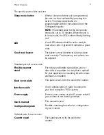
The specific parts of this unit are: 

Sleep mode button 

-


When a sleep mode time-out is programmed,

the unit

 can be re-activated by pressing this

switch. The sleep mode feature is
programmable with the menu labels from the
Configuration guide.

NOTE:

 The default value for the sleep mode

time-out is set to 30 minutes. When 

the unit

 is

in sleep mode, the LED is intermittently flashing
red.

LED 

Good read buzzer 

-

A red LED indicates that 

the unit

 is ready to

read a bar code. A green LED indicates a good
read.

-

The buzzer is heard whenever data has been

read correctly. The frequency and volume can
be adjusted

Standard parts & accessories: 

Flexible scanner 
stand 

Back cover plate 

Interface cable 

Power supply 

User’s manual 

Configuration guide 

-

The rotary and flexible stand allows you to

direct the scan pattern in a way that is optimal
for your application (a mounting kit with screws
and tapes is included).

-

This plate serves to fix 

the unit

 to the


counter.

-

One of various types of cable to connect to

your host computer / POS system.

-

Powers your scanner via the AC power outlet if

your scanner is not directly powered.

-

This manual in print

-

Booklet containing barcodes for configuration

of your scanner

Optional parts & accessories: 

Counter stand 

-


The stand serves to fix 

the unit

 to the

counter.

Содержание EC-OS-7200D

Страница 1: ......

Страница 2: ...User s Manual...

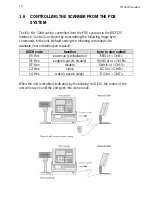
Страница 3: ...se limits are designed to provide reasonable protection against harmful interference when the equipment is operated in a commercial environment This equipment generates uses and can radiate radio freq...

Страница 4: ...OS system 11 Chapter 2 Installation 13 2 1 Connecting the scanner 14 2 2 Interface selection 16 2 3 Installing the scanner on a counter surface 17 2 4 Installing the scanner with the counter stand 19...

Страница 5: ...by pressing the switch on top of the unit This unit is available in two colour versions both supporting multiple interface for communication with any host system The multiple interface versions are RS...

Страница 6: ...Chaper 1 Product Overview...

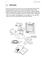
Страница 7: ...red Visually inspect the unit and accessories for any evidence of physical damage Refer to the upper figure on page 5 to locate the interface label and make sure that the unit interface corresponds wi...

Страница 8: ...data has been read correctly The frequency and volume can be adjusted Standard parts accessories Flexible scanner stand Back cover plate Interface cable Power supply User s manual Configuration guide...

Страница 9: ...3 Electrical Safety EN 60950 1992 IEC 950 1991 EMC EN 55022 2006 A1 2007 EN 61000 3 2 2006 EN 61000 3 3 1995 A1 2001 A2 2005 EN 55024 1998 A1 2001 A2 2003 IEC 61000 4 2 1995 A1 1998 A2 2000 IEC 61000...

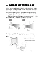
Страница 10: ...is illustrated in the figure below The optimal reading zone lies between 2 and 15 cm from the unit window but bar codes can be read up to 30 cm 11 8 in from the unit window If a scanner with flexible...

Страница 11: ...are also visible through the unit window All labels are attached by the manufacturer and should not be removed The unit s serial number is found underneath the bar code label as depicted in the figure...

Страница 12: ...serlys i l ngere perioder Finnish Skanneri t ytt luokan I lasertuotteelle IEC 825 1 ss 1993 asetetut turvavaatimukset Se t ytt my s U S 21CFR1040 ssa asetetut vaatimukset silt osin kuin ne koskevat lu...

Страница 13: ...served at 13 cm 5 1 in above the window through a 7 mm 0 28 in aperture and averaged over 1000 seconds is less than 3 9 W per CDRH Class IIa specification Do not attempt to remove the protective housi...

Страница 14: ...ANNER The unit requires little maintenance Only occasional cleaning of the unit window is necessary to remove dirt and fingerprints Cleaning can be performed during operation with a non abrasive glass...

Страница 15: ...tting the following commands are available more details upon request ASCII code function byte is also called 05 Hex power up re initialization ENQ or Ctrl E OE Hex enable cancels disable Shift Out or...

Страница 16: ......

Страница 17: ...Chapter 2 Installation...

Страница 18: ...and the host system must be switched off before starting the installation of the unit By following this precaution you prevent any electrical damage You are advised to install the unit in an air circu...

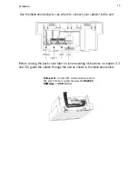
Страница 19: ...e unit Before closing the back cover later on see mounting instructions in chapter 2 3 and 2 4 guide the cables through the unit as shown in the illustration below Data port 1 Connect the communicatio...

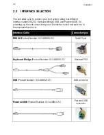
Страница 20: ...Powered USB On powering up the unit senses the type of the interface used and switches to the appropriate protocol Interface Cable Connector type RS232 Product Number 0114 S806121 Sub D 9 pin Keyboard...

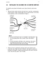
Страница 21: ...can use the back cover as a template to mark the places for the mounting holes at the counter surface and drill two holes If you do not want to drill holes in the counter top the unit can be installe...

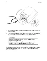
Страница 22: ...tlet Switch on the host system IMPORTANT To activate USB or KBW interface scan the following codes from the Configuration Guide 1 Open the unit Programming Mode by scanning code 1 1 2 Return to factor...

Страница 23: ...n start scanning bar code labels If you want to change the default settings of the unit proceed to the Configuration Guide which came with the unit 2 5 INSTALLING THE SCANNER USING THE FLEXIBLE SCANNE...

Страница 24: ...hole NOTE If you prefer not to drill in your counter you can mount the stand using the provided double sided tape and have the cables leave the foot at the rear just above the circular basis 4 Fix th...

Страница 25: ...he foot of the stand 10 Connect the data cable to the host 11 Place the unit in the desired angle In case you have an external power supply plug the power supply into an AC power outlet 12 Switch on t...

Страница 26: ...PLATE To remove this unit from the back cover plate that is either attached on the counter or on the scanner stand 1 Locate the small hole at the back cover of the unit 2 Remove the back cover by pre...

Страница 27: ...Appendices A Connector types and pin definitions B Technical Specifications C Troubleshooting...

Страница 28: ...the unit 2 Scan the following codes from the Configuration Guide Open the unit Programming Mode by scanning code 1 1 Return to factory default settings by scanning code 1 3 Pin definitions for multi i...

Страница 29: ...tion Pin Description Direction 1 5 VDC output 1 2 CTS input 2 3 RXD input 4 reserved 5 RTS output POWER 6 GND Pin Description Direction 7 reserved 1 12V input 8 reserved 2 GND 9 reserved 10 reserved T...

Страница 30: ...Appendices 26...

Страница 31: ...Interfaces RS 232 USB Powered USB Keyboard Wedge Optical Light source Visible laser diode 650 nm Depth of field 330 mm Scan pattern 7 directions scan field 24 lines scan pattern Scan rate 2000 scans s...

Страница 32: ...5 x 5 31 inch Environmental Operating temperature 0 C 40 C Humidity 20 95 RH non condensing Safety Laser safety IEC 825 1 1993 Class I U S CDRH 21CFR1040 Class II a Electrical safety EN 60950 second e...

Страница 33: ...is disabled by the host Refer to Section 1 6 The bar code type you presented to the unit is not supported by the unit The unit is on but the motor is not rotating A bar code cannot be read The LED is...

Страница 34: ...unit and the host Scanner buffer is full Make sure that all cables are connected and your host system is ready to receive data A bar code is read by the unit but not accepted by the host system The co...

Страница 35: ...install some general drivers possibly from your computer setup CD In case of KB emulation you can select various keyboard languages or the universal Alt input method In a windows environment verify wi...

Страница 36: ......

Отзывы: