LAN Gateway Firmware V1.2
V1.8 25. April 2012
© 2012 – ECKELMANN AG | BERLINER STRASSE 161 | 65205 WIESBADEN | PHONE +49(0)611 7103-0 | FAX +49(0)611 7103-133 | eckelmann.de
18/34
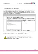
4.5.3 Configuration of the CAN bus address
On leaving the factory, the LAN gateway is configured to the CAN bus address
127
. This configuration enables
the parallel operation with
one
CAN bus-PC adapter (address 126). However in this configuration, no terminal
mode via the LAN gateway is possible with CI 3000 store computers older than the version 4.11. In this case,
the LAN gateway CAN bus address can be changed as described below. Parallel operation with a CAN bus-PC
adapter is then no longer possible due to the address conflict.
Step
PC procedure
1.
Activate the monitor interface as described in chapter 4.2.2.
2.
Enter the command “
canconf
“ and
ENTER
in the console.
3.
The current CAN bus address is displayed. Call up the dialog for entering a new CAN bus address by
entering “
y
“ and
ENTER
or terminate the configuration by entering „
n
“ and
ENTER
.
4.
Only the CAN bus addresses 126 or 127 can
be assigned.
Input scheme:
•
0 => 126
•
1 => 127
5.
Confirm changes by entering “
y
“ and
ENTER
or abort by entering “
n
“ and
ENTER
The CAN bus address 126 is only designed for systems containing a store computer with a firmware version
lower than 4.17. However, in this case, an update of the store computer is preferable.
Due to restrictions in the firmware of the CI 3000 store computer a reliable
integration of the LAN gateway in the node monitoring function is only possible under
the CAN bus address 127!
Bei Vergabe der CAN-BUS-Adresse 126 muss die Priorität auf 0 (Meldeliste) gesetzt
werden!
The configuration of the CAN bus address has an effect on the behaviour of the LAN
gateway within the node monitoring and failure alarm functions. For a comprehensive
monitoring of the LAN gateway by the store computer and/or alarm terminals, the address
must be set to 127. See also chapter


