FLDS
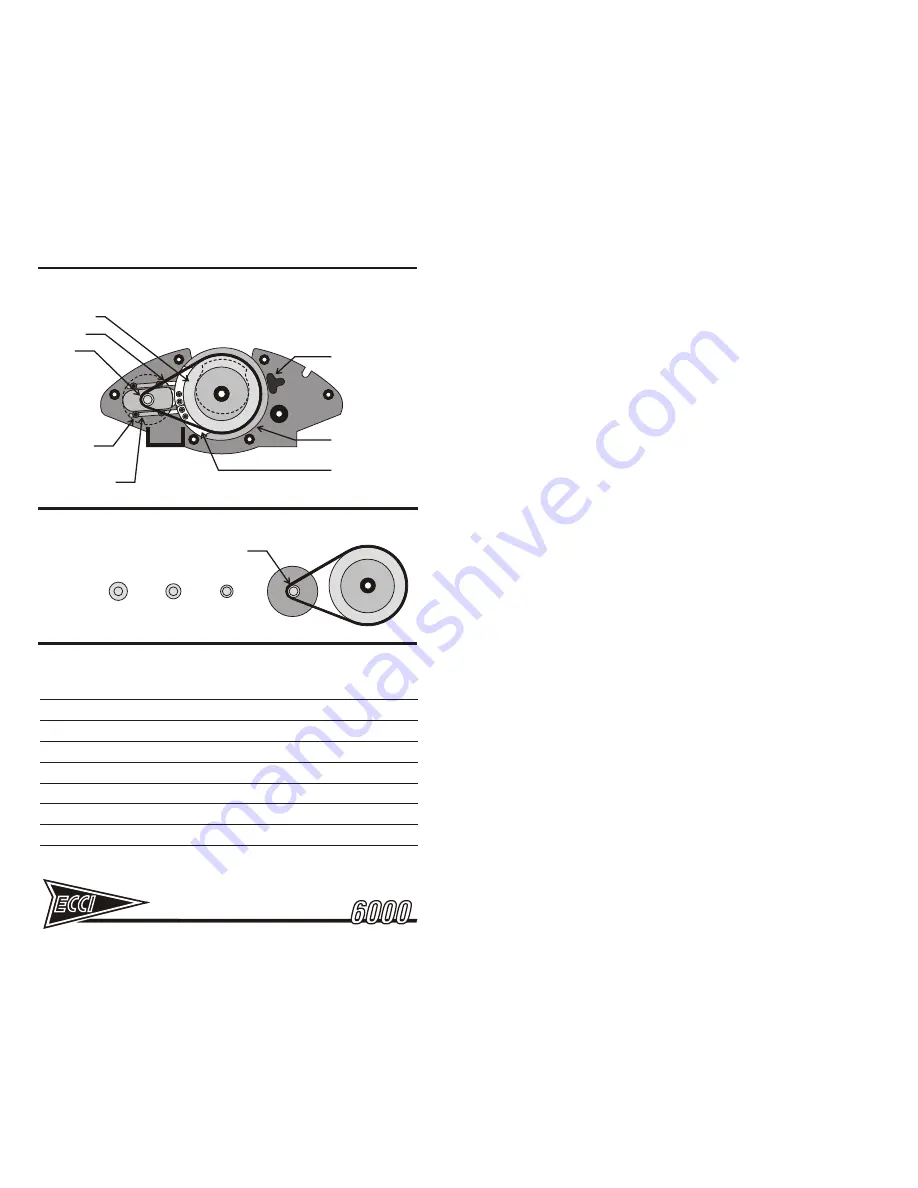
Figure 26 - FLUID DAMPED STEERING SYSTEM
Figure 27 - DAMPING ADJUSTMENT OPTIONS
DRIVE BELT
DRIVE PULLEY
DAMPER
PULLEY
DAMPER BELT
TENSIONING SLOTS
FLDS ROTARY
FLUID DAMPER
STANDARD
LIGHT
LIGHTEST
RESISTANCE CAM, FOLLOWER ARM,
AND SPRING ASSEMBLY REMOVED
DAMPER
PULLEY
FROM THIS VIEW FOR CLARITY
NOTE:
WHEEL TRAVEL
LIMITER
TRAVEL
ADJUSTMENT STOPS
MAIN STEERING
STOP
TRACKSTAR
NOTES:
6.0
POT REPLACEMENT AND POT SETUP
The following steps are required only if replacing pots. Pots are the electro-
mechanical components that sense the position of the wheel or pedal and
translate this to electrical information read by the ECCI USB HD system. These
are long-lived but will eventually wear out. The sign of pot wear is notchy,
inconsistent response at the same spot in the axis travel. If the problem is
variable, occurring in different areas of travel at different times, the problem may
instead be a loose pot shaft nut or a loose wire connector. Pots that do not
maintain calibration can also be caused by a loose not. Rule these things out first
before ordering new pots.
If you need new pots,
use only ECCI pots
. ECCI pots are specifically made for
ECCI controllers and have the required resistance range and performance
characteristics. ECCI cannot warrant the performance of any system not using
ECCI pots. When ordering replacements, order the ECCI HP Racing pots. The
USB HD needs a 100K HP pot for the steering and 50K HP pots for the pedals.
Unless you have a rare premature failure (under 1 year), ECCI recommends
replacing the entire set rather than the single pot with the problem.
6.1
STEERING POT REPLACEMENT
Replacing the wheel pot is a simple procedure. Refer to Figures 6 and 28 for
illustrations. The steps to perform replacement are as follows:
1. Mount the wheel unit securely to a tabletop with the clamp. Unplug the USB
cable from your computer. Remove the ten screws which secure the cover of
the wheel unit to the chassis. Lift the cover and set aside.
2. Leave the pedal unit and its associated ground cable attached to the wheel
unit. This will provide ground protection for the circuit board. If your pedal
unit is not attached, use the ground cable originally supplied with your
driving system to connect the steering unit chassis to a screw on the
computer case, a screw attached to the faceplate of an electrical outlet, or
other suitable ground.
3. Carefully pull the wire connectors from the pot terminals. Make sure to pull
on the connector body, not the wire.
4. Using a 3/32” hex key, loosen the steering shaft clamping screw located on
the pot connector [Figure 28]. Next use a philips screwdriver to remove the
pot bracket screws. The pot bracket assembly can now be removed.
5. Loosen the pot shaft clamping screw on the pot connector. Slide the
connector free and remove the pot retaining nut and the pot will fall free.
6. Mount the new replacement pot, into the pot bracket using the nut and lock
washer. Make sure the pins in the pot body engage the slots in the bracket.
Turn the retaining nut down until tight. Avoid over-tightening as this can
damage the pot. Turn the pot shaft so the slot is vertically in-line with the
center terminal of the pot. The slot must be vertical for the next step.
Next examine the pot connector. Note that at each end, the clamping
screw tightens a split in the ends of the connector. The split in the
connector must be horizontal with the clamping screws facing upward,
Making sure the pot


