27
Overview
Flame monitor
IR Flame Detector FFS 06
For IR flame detectors and UV flame
detectors, the minimum response thres-
holds are 15 mV AC and 25 mV AC,
respectively. Refer to the technical
documentations of the flame monitors
for further commissioning instructions.
Note: The UV flame detectors are not
provided with this sensitivity adjust-
ment. They are optimized by aligning to
the flame to be monitored in the best
possible way using the measurable
signal voltage on the measuring line.
Criteria for flame detectors
Detector type
spectral radiation range
application - fuel
FFS 06 UV-1
260-400nm
oil, gas
FFS 06 UV-2
210-380nm
oil, gas (special gases such as
refinery and high furnace gases)
FFS 06 (IR)
1200-2800nm
oil, gas, furnaces with heavy flue
gas recirculation, waste gases
with yellowish colouring without
UV radiation
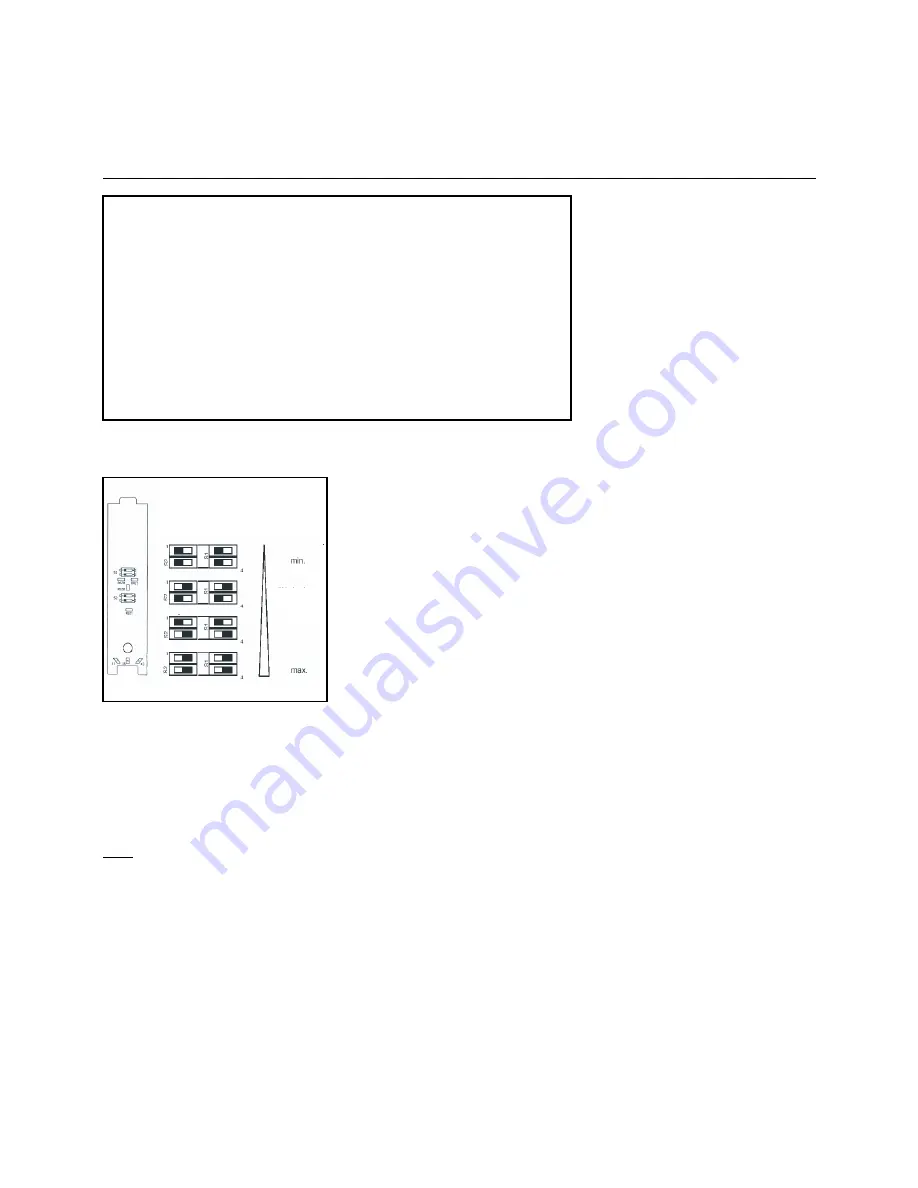
Sensitivity
Adjustment to be made on switches
S1 and S2 which are accessible
after opening the detector housing.
factory
configur-
ation
Figure 2
Assembling and commissioning of
flame detectors
The flame detector should be installed
in the provided mounting at an inspec-
tion opening of the burner in a way that
the burner flame to be monitored is
clearly visible in the overall operational
range of the furnace. The sensitivity of
the IR flame detector FFS 06 to the bur-
ner flame can be adapted via the thres-
hold switch in the flame detector. In
doing so, the sensor housing should be
unscrewed and the setting on the thres-
hold switches made according to the
Figure (2).


