background image

Chengdu Ebyte Electronic Technology Co., Ltd.

E22-400T30S_User Manual _EN

Copyright ©2012–2020, Chengdu Ebyte Electronic Technology Co., Ltd.

12

3

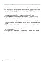
After the user switches to a new working mode, at least 2ms after the rising edge of AUX, the module will actually enter

this mode;

If AUX is always at high level, then the mode switch will take effect immediately.

4

When the user enters other modes from mode 3 (sleep mode) or during the reset process, the module will reset the user

parameters, during which AUX outputs low level.

5

Due to the characteristics of the LoRa modulation method, the information transmission delay is much longer than that of

FSK. For example, at an airspeed of 1.2kbps, the transmission delay of 100 bytes is about 1.5 seconds. It is recommended

that customers do not transmit large amounts of data at low airspeeds. , so as to avoid communication anomalies caused by

data loss caused by data accumulation.

Chapter 6 Working Mode

The module has four working modes, which are set by pins M1 and M0; the details are shown in the table below:

Mode

0-3

M1 M0

Mode Introduction

Remark

0 Transfer Mode

0

0

Serial port open, wireless open, transparent transmission

Support special command

air configuration

1 WOR Mode

0

1

Can be defined as WOR sender and WOR receiver

Support air wake

2 Configuration

Mode

1

0

Users can access the registers through the serial port to control the

working status of the module

3 Deep Sleep

1

1

Module goes to sleep

6.1 Mode Switch

No

Remark

1

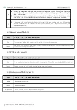
The user can combine the high and low levels of M1 and M0 to determine the working mode of the module. 2 GPIOs of

MCU can be used to control mode switching;

After changing M1 and M0: If the module is idle, it can start working in the new mode after 1ms;

If the serial port data of the module has not been transmitted wirelessly, the new working mode can only be entered after

the transmission is completed;

If the module receives the wireless data and sends out the data through the serial port, it needs to send the data before

entering the new working mode;

So the mode switch can only be valid when AUX output 1, otherwise the switch will be delayed.

2

For example: the user continuously inputs a large amount of data and simultaneously performs mode switching. At

this time, the switching mode operation is invalid; the module will process all user data before performing new mode

detection;

Therefore, the general suggestion is: detect the output state of the AUX pin, wait for 2ms after outputting a high level,

and then switch.

3

When the module is switched from other modes to sleep mode, if there is data that has not been processed;

The module will enter the sleep mode only after processing the data (including receiving and sending). This feature can

be used for fast sleep to save power consumption; for example: the transmitter module works in mode 0, the user

initiates serial port data "12345", and then does not have to wait for the AUX pin to be idle (high level), it can directly

switch to sleep mode, And the main MCU of the user will sleep immediately, and the module will automatically enter

the sleep within 1ms after sending all the user data through wireless;

Thereby saving the working time of the MCU and reducing power consumption.

Содержание E22-400T30S

Страница 1: ...E22 400T30S User Manual SX1262 433 470MHz 1W LoRa Wireless Module...

Страница 2: ...ENING ADDRESS 10 5 5 MODULE RESET 10 5 6 DETAILED EXPLANATION OF AUX 10 5 6 1 Serial Port Data Output Indication 10 5 6 2 Wireless Transmission Indication 11 5 6 3 The module is being configured 11 5...

Страница 3: ...ngdu Ebyte Electronic Technology Co Ltd 2 CHAPTER 12 WELDING OPERATION INSTRUCTIONS 22 12 1 REFLOW TEMPERATURE 22 12 2 REFLOW SOLDERING PROFILE 22 CHAPTER 13 RELATED MODELS 23 CHAPTER 14 ANTENNA GUIDE...

Страница 4: ...estoppel or otherwise The test data obtained in this article are all obtained from Ebyte laboratory tests and the actual results may be slightly different All trade names trademarks and registered tr...

Страница 5: ...ead which greatly improves the confidentiality of user data Support LBT function monitor the channel environment noise before sending which can greatly improve the communication success rate of the mo...

Страница 6: ...nology Co Ltd 5 1 3 Application Scenario Home security alarm and remote keyless entry Smart home and industrial sensors etc Wireless alarm security system Building automation solutions Wireless indust...

Страница 7: ...ustrial design Working frequency band MHz 410 125 493 125 Support ISM frequency band power consumpt ion Emission current mA 610 Instantaneous power consumption Receive current mA 17 Sleep current uA 2...

Страница 8: ...not floating if not used it can be grounded 3 RXD Input TTL serial port input connected to the external TXD output pin 4 TXD Output TTL serial port output connected to external RXD input pin 5 AUX Ou...

Страница 9: ...eeds to be suspended for subsequent expansion 14 P1 6 Input Output NC pin this pin needs to be suspended for subsequent expansion 15 GND Fixedly 16 GND Fixedly 17 GND Fixedly 18 ANT Output Antenna int...

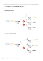
Страница 10: ...e Electronic Technology Co Ltd E22 400T30S_User Manual _EN Copyright 2012 2020 Chengdu Ebyte Electronic Technology Co Ltd 9 Chapter 5 Function Detailed Explanation 5 1Fixed point launch 5 2 Broadcast...

Страница 11: ...is powered on AUX will output low level immediately and perform hardware self test and set the working mode according to user parameters During this process AUX keeps low level and after the completi...

Страница 12: ...for the end of user data to time out or it is transmitting wireless packets Note When AUX 1 it does not mean that all serial port data of the module has been transmitted wirelessly or the last packet...

Страница 13: ...h and low levels of M1 and M0 to determine the working mode of the module 2 GPIOs of MCU can be used to control mode switching After changing M1 and M0 If the module is idle it can start working in th...

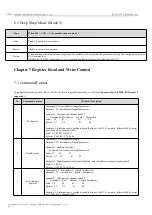
Страница 14: ...uce the workload of the entire system as much as possible improve system efficiency and reduce power consumption 6 2 General Mode Mode 0 Type When M0 0 M1 0 the module works in mode 0 Send Users can i...

Страница 15: ...gth parameter Response C1 start address length parameter Example 1 Configure the channel as 0x09 Command Start Address Length Parameters Send C0 05 01 09 Return C1 05 01 09 Example 2 Simultaneously co...

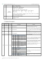
Страница 16: ...g at this time 01H read write ADDL ADDL default 0 02H read write NETID NETID default 0 Network address used to distinguish the network When communicating with each other they should be set to be the s...

Страница 17: ...able 4 3 2 reserve 1 0 transmit power The relationship between power and current is non linear and the power supply efficiency is the highest at maximum power Current does not decrease proportionally...

Страница 18: ...WOR cycle Only valid for mode 1 Period T 1 WOR 500ms maximum 4000ms minimum 500ms The longer the WOR monitoring interval period the lower the average power consumption but the greater the data delay...

Страница 19: ...vel Relay networking rules description 1 Forwarding rules the relay can forward data in both directions between two NETIDs 2 In relay mode ADDH ADDL is no longer used as a module address but as a NETI...

Страница 20: ...er A is 02 and the network ID input by the receiver B is 10 then when the relay terminal R sets the module address convert the hexadecimal value 0X020A to the decimal value 522 and fill it in as the r...

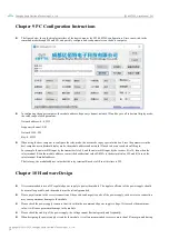
Страница 21: ...ound the module that will greatly affect the performance of the module According to the intensity of the interference it is recommended to keep away from the module If the situation permits proper iso...

Страница 22: ...ower the output power The matching degree between the antenna and the module is poor or the quality of the antenna itself is problematic 11 2 Modules are easily damaged Please check the power supply t...

Страница 23: ...t temperature max Tsmax Max preheating temperature 150 200 Preheat Time Tsmin to Tsmax ts Preheat time 60 120 sec 60 120 sec Average ramp up rate Tsmax to Tp Average rate of ascent 3 second max 3 seco...

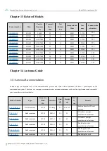
Страница 24: ...12 SMD 24 38 5 SPI Chapter 14 Antenna Guide 14 1 Antenna Recommendation Antennas play an important role in the communication process and often inferior antennas will have a great impact on the communi...

Страница 25: ...tenna cost effective TX433 XP 200 Suction cup antenna 433M SMA J 4 0 190 200 Neutral suction cup antenna low loss TX433 XPH 300 Suction cup antenna 433M SMA J 6 0 965 300 Large suction cup antenna hig...

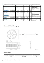
Страница 26: ...2 2018 05 24 Name change Huaa 1 3 2018 07 20 Model split Huaa 1 4 2018 10 23 Content update Ray 1 5 2019 04 03 Content update Ray 1 9 2022 12 7 Error correction Yan About US Sales Hotline 4000 330 99...

Отзывы: