12
EP100 Master Instruction
_____________________________________________________
D00002-C-04
7 START-UP
7.1 General
First of all, the nameplate should be checked,
especially with respect to references to Ex / non- Ex,
input signal, single / double acting.
Before starting the positioner the EP100 has to be
mounted to the actuator; an input signal 4 to 20 mA or
split range have to be available. The supply air
connection must have sufficient capacity and
pressure of 1.4 to 6 bar (20 to 90 psig) and should not
exceed the maximum operating pressure of the
actuator.
The EP100 can be adjusted by means of switches
and potentiometers when the housing cover is
opened.
Attention:
Configuration using switches and
potentiometers may interfere with operation of the
actual process! During configuration it is
recommended that there is no flow through the
valve.
At initial start-up various adjustments have to be set.
The following procedure is recommended:
Setting of
direction of rotation
of feedback lever
(chapter 7.2)
Setting of
input signal range
e.g. 4 to 20 mA or
split range (chapter 7.3)
Setting of
gain
(chapter 7.4)
Setting of
zero and span
(chapter 7.5)
Setting of
damping
(time constant, chapter 7.6)
The
position indicator
12 is attached to the
desired position after selection of the
transmission at indicator shaft (chapter 7.7)
The
air capacity throttles
at the pneumatic
output (screws 17 and 18 underneath of the
SERVICE openings) are factory-set to the
operating value and are normally not reset
(exception see chapter 7.8).
When attaching the
housing cover
make sure
that the venting opening points to the bottom
Settings via switches and potentiometers
For the setting of the EP100 and the adjustment of
various parameters 8 dip switches and 5
potentiometers are available.
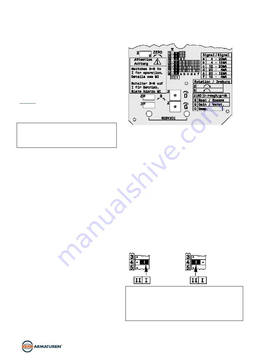
See electronics imprint as follows:
1) Adjustment of electronic board (in workshop, see page 17)
The potentiometers are for the setting of:
Zero point (ZERO): P3
Span (S): P2
Gain (G): P4
Damping (D): P5
Electronics alignment: P1
1)
Single-threaded potentiometers with limited rotation angle to
set gain (G) and damping (D) are available, where the actual
position is indicated by an arrow. To set zero point (ZERO),
span (S) and the electronics alignment
1)
multiplethreaded
potentiometers (approx. 30 rotations) without rotation
limitation are used.
The
switches
are for the setting of:
Direction of rotation of feedback lever (switches 1, 2)
Electronics adjustment (switch 3)
1)
Signal range (switches 4, 5, 6 and 7)
Pneumatic test (switch 8)
The switch numbers (1 through 8) are imprinted on the
electronics. The possible switch position (“I” and “II”) are
imprinted below switch 8. The switch positions are defined as
follows:
Switch Position
“I”:
Switch Position II:
Caution!
Switches 3 and 8 must be during operation in position “I”.
Prior to resetting switches 1 to 8 it is recommended to shut-
off the respective part of the installation since processes are
activated influencing and disturbing the current process.
Therefore, it is recommended that no medium flows through
the valve during configuration..


