


STEERING HEAD LOCK
Protect your vehicle against theft. After parking your
motorcycle, lock the steering head and remove igni-
tion key from switch. Failure to lock your motorcycle
may result in theft and/or equipment damage.
The steering head lock is located on the ignition/
headlamp key switch and is operated by the ignition key.
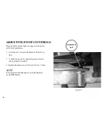
1. Verify sidestand is down. Turn handlebars full left.
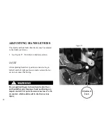
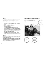
2. See Figure 3. Verify that key is in the OFF position.
3. Push in on the ignition key and turn it counterclock-
wise to the steering head LOCK position. Move handle-
bars slightly until locked.
4. Attempt to turn the handlebars to the right to verify
that the steering head is locked. Handlebars should not
turn.
5. Remove key from the ignition/headlamp key switch.
This motorcycle does NOT have a locking sidestand.
Park the motorcycle on a level, firm surface. An un-
balanced motorcycle can fall, which could result in
death or serious injury.
The sidestand is located on the left side of the motorcy-
cle and swings down to support the motorcycle for park-
ing.
Be sure side stand is fully retracted before riding. If
side stand is not fully retracted, it can contact the
road surface causing a loss of vehicle control, which
could result in death or serious injury.
SIDESTAND
Figure 27
72
Содержание EBR 1190RS 2013
Страница 1: ...2013 EBR OWNERS MANUAL EBR 1190RS MODEL Part Number C1000 2B6 1 ...
Страница 3: ...3 ...
Страница 23: ...TABLE OF CONTENTS Notes 23 ...
Страница 24: ...TABLE OF CONTENTS Notes 24 ...
Страница 36: ...VEHICLE IDENTIFICATION NUMBER EBR 1190RS MODELS 36 ...
Страница 39: ...NOTES 39 ...
Страница 42: ...Table 5 Drivetrain Table 6 Cooling System Table 7 Liquid Capacities Table 8 Sprocket teeth 42 ...
Страница 43: ...Table 9 Transmission Gear Ratios Table 11 Tires Table 10 Bulb Chart 43 ...
Страница 44: ...Table 12 Dimensions Table 13 Weights 44 ...
Страница 64: ...Table 15 64 ...
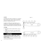
Страница 66: ...Figure 24 Upshift Pattern Figure 25 Downshift Pattern 66 ...
Страница 71: ...Maximum Fill Level is at Bottom of Baffle Figure 29 71 ...
Страница 84: ...Figure 34 Seat Fasteners Seat removal 4 T 30 screws 84 ...
Страница 92: ...92 Notes ...
Страница 93: ...93 Notes ...
Страница 111: ...Figure 47 Engine oil drain plug left side Figure 48 Engine oil drain plug Right side Drain Plug Drain Plug 111 ...
Страница 116: ...Figure 52 Adjustment Measurement 35 mm Adjustment Distance 116 ...
Страница 117: ...117 Notes ...
Страница 176: ...176 ...
Страница 177: ...177 ...
Страница 178: ...178 ...


