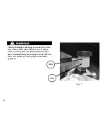


HEADLAMP ALIGNMENT
The automatic-on headlamp feature provides in-
creased visibility of the rider to other motorists. Be
sure headlamp is on at all times. Poor visibility to
other motorists can result in death or serious injury.
NOTE
This vehicle has beam headlamps that are individually
aimed and should be adjusted so both lamps converge
into one pattern.
1. Verify that front and rear tire inflation pressures are
correct and that suspension is adjusted to the weight
of the principal rider. See SPECIFICATIONS.
2. Fill fuel tank or add ballast to equal the weight of
fuel needed.
NOTE
See Figure 60. To aid in properly placing the motorcy-
cle, a perpendicular line can be drawn on the floor. For
best results, choose an area with minimum light.
3. See Figure 60. Draw a vertical line on the wall.
4. Position motorcycle so that the front axle is 25
feet (7.6 meters) from the wall.
NOTE
As the weight of the rider will compress the suspen-
sion slightly, have a person whose weight is approxi-
mately the same as that of the principal rider sit on the
motorcycle.
5. With the motorcycle laden and upright, point the
front wheel straight forward at the wall and meas-
ure the distance from the floor to the center of the
LOW BEAM bulb.
6. Draw a horizontal line through the vertical line on
the wall that is 2.1 in. (53.3mm) lower than the
measured bulb centerline.
143
Содержание EBR 1190RS 2013
Страница 1: ...2013 EBR OWNERS MANUAL EBR 1190RS MODEL Part Number C1000 2B6 1 ...
Страница 3: ...3 ...
Страница 23: ...TABLE OF CONTENTS Notes 23 ...
Страница 24: ...TABLE OF CONTENTS Notes 24 ...
Страница 36: ...VEHICLE IDENTIFICATION NUMBER EBR 1190RS MODELS 36 ...
Страница 39: ...NOTES 39 ...
Страница 42: ...Table 5 Drivetrain Table 6 Cooling System Table 7 Liquid Capacities Table 8 Sprocket teeth 42 ...
Страница 43: ...Table 9 Transmission Gear Ratios Table 11 Tires Table 10 Bulb Chart 43 ...
Страница 44: ...Table 12 Dimensions Table 13 Weights 44 ...
Страница 64: ...Table 15 64 ...
Страница 66: ...Figure 24 Upshift Pattern Figure 25 Downshift Pattern 66 ...
Страница 71: ...Maximum Fill Level is at Bottom of Baffle Figure 29 71 ...
Страница 84: ...Figure 34 Seat Fasteners Seat removal 4 T 30 screws 84 ...
Страница 92: ...92 Notes ...
Страница 93: ...93 Notes ...
Страница 111: ...Figure 47 Engine oil drain plug left side Figure 48 Engine oil drain plug Right side Drain Plug Drain Plug 111 ...
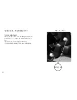
Страница 116: ...Figure 52 Adjustment Measurement 35 mm Adjustment Distance 116 ...
Страница 117: ...117 Notes ...
Страница 176: ...176 ...
Страница 177: ...177 ...
Страница 178: ...178 ...


