


15
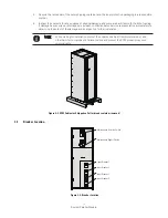
System Parallel Module
4 .3
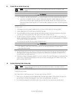
External Power Cables Connecting
WARNING
WARNING
Verify phases of connections. Risk of personal injury and damage to equipment from arc flash if
connections are reversed.
•
TURN OFF UPS AND DISCONNECT UPS FROM POWER SUPPLY BEFORE SPM INSTALLATION.
•
HIGH TOUCH CURRENT. EARTH CONNECTION MUST BEFORE CONNECTING SUPPLY. As a
result of the connected loads high leakage current is possible. Connection of the earth (ground) is
required for proper product operation. Do not check UPS operation by removal of the Earth (ground)
connection.
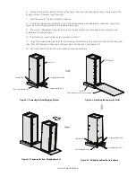
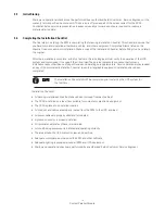
To install wires:
1. If installing wiring using conduit, please punch or drill hole on the bottom and top cover plates.
2. Install conduit between the UPS cabinet and SPM if needed.
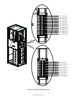
3. Ground the SPM according to local and/or national electrical wiring codes by routing and connecting the
ground wire to the input ground lug. See Figure 4-5 for SPM terminal locations.
4. Route and connect the power cables(L1,L2,L3,N) from the utility source to the SPM phase and terminal
blocks. See Figure 4-5 for wiring access information and terminal locations. See paragraph 3.2.2,Table 3-3
for wiring and termination requirements.
The utility source must be the same as the UPS bypass input.
5. Route and Connect the power cables(L1,L2,L3,N ) from the Load to the SPM phase and terminal blocks.
See Figure 4-5 for wiring access information and terminal locations. See paragraph 3.2.2,Table 3-3 for
wiring and termination requirements.
6. 5 Route and Connect the power cables(L1,L2,L3,N ) from the UPS to the SPM phase terminal blocks. See
Figure 4-5 for wiring access information and terminal locations. See paragraph 3.2.2,Table 3-3 for wiring
and termination requirements.
Wires enter/out from the bottom conduit landing plate or knock-out holes on 2 side
plates.
NOTE
4 .4
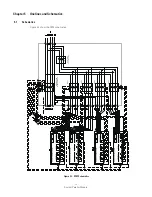
External Signaling Cables Connecting
To install the signal wires:
Refer figure 4-6 to install the signal wires. The wire code is minimum 22AWG.
1. Please refer to the appropriate Eaton 93E80-200kVA and 93PM 50-200kW UPS installation and operation
manual listed in corresponding paragraph for pull chain and building alarm connections.
2. To located the appropriate terminals and review the wiring and terminal requirement see Figure 4-6.
To avoid the interface between the power cables and signal wires, please route the
cables separate.
NOTE
Содержание SPM 120
Страница 1: ...System Parallel Module Installation and Operation Manual Eaton UPS Accessories...
Страница 2: ......
Страница 25: ...19 System Parallel Module Notes...
Страница 29: ......
Страница 30: ......
Страница 31: ......
Страница 32: ...614 01728 00...


