background image


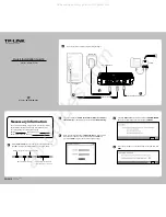
Useful info about Alarm Contacts in PXES6P :  

 
1. Two-position terminal block (1,2) provided next to the DC power input, as shown above. 
2. The Alarm Relay contact connected to the two terminals (1,2) is hardware operated. 
3. By default it is NC (normally closed). It will open if there is any loss of power to the 
electronics inside of the unit. 

 
5.0 TROUBLESHOOTING 


All Ethernet products are designed to provide reliability and consistently high 

performance in all network environments.  The installation of PXES6P Series 10/100 Mb/s 

Switches is a straightforward procedure (see INSTALLATION, Section 3.0); the operation is 

also straightforward and is discussed in Section 4. 


Should problems develop during installation or operation, this section is intended to 

help locate, identify and correct these types of problems.  Please follow the suggestions listed 

48 


below prior to contacting your supplier.  However, if you are unsure of the procedures described 

in this section or if the PXES6P Series 10/100 Mb/s Switch is not performing as expected, do not 

attempt to repair the unit; instead contact your supplier for assistance or contact EATON 

Customer Support. 

5.1


Before Calling for Assistance 


1.


If difficulty is encountered when installing or operating the unit, refer back to the 

Installation Section of the applicable chapter of this manual.  Also check to make 

sure that the various components of the network are interoperable. 

2.


Check the cables and connectors to ensure that they have been properly   

                connected and the cables/wires have not been crimped or in some way  

                impaired during installation.  (About 90% of network downtime can be  

                attributed to wiring and connector problems.) 

49 


3.


If the fiber port does not link up while connecting to other device, do a quick 

Loop test to test the fiber transceiver is functional or not. Use a short patch cable 

of fiber and connect one end of cable to transmit and other end of receive to the 

fiber port transceiver. If the Link LED turns solid green, then the fiber port is 

functional and working. 

4.


Make sure that an AC power cord is properly attached to each PXES6P Series 

unit.  Be certain that the AC power cord is plugged into a functioning and 

appropriate electrical outlet.  Use the PWR LEDs to verify each unit is receiving 

power. 

5.


If the problem is isolated to a network device other than the PXES6P Series 

10/100 Mb/s switch product, it is recommended that the problem device is 

replaced with a known good device.  Verify whether or        not the problem is 

corrected.  If not, go to Step 6 below.  If the problem is        corrected, the 

PXES6P Series Switch and its associated cables are functioning properly. 

6.            If the problem continues after completing Step 5 above, contact your supplier  

50 

Содержание PXES6P24V1ST

Страница 1: ...duced without prior written permission from Eaton Printed in the United States of America 1 Federal Communications Commission Radio Frequency Interference Statement This equipment generates uses and c...

Страница 2: ...PXES6P with 24VDC power input 33 3 6 PXES6P Series 24VDC powered Installation 34 3 7 Connecting Ethernet Media 35 4 3 8 Connecting Twisted Pair RJ 45 CAT 3 or CAT 5 Unshielded or shielded 36 3 8 1 Con...

Страница 3: ...to flush the internal address buffer and qualify to use with S Ring and RSTP for faster recovery in ring topology Maximum Ethernet Segment or Domain Lengths 10BASE T Unshielded twisted pair 100 m 328...

Страница 4: ...ory floor temperature rated Input 6ft AC 3power cord to IEC 320 connector on the 100 240vac 47 63Hz external power adapter Output 12vdc 1 25Amps Direct DC POWER SUPPLY Built in terminal Block for grou...

Страница 5: ...n PXES6P24V1ST 66A2303G01 6 port Ethernet Switch 5 copper 1 fiber ST PXES6P24V2ST 66A2305G01 6 port Ethernet Switch 4 copper 2 fiber ST PXES6P24V 66A2306G01 6 port Ethernet Switch copper only Accessor...

Страница 6: ...s and is able to be conveniently DIN rail mounted to suit any application The Power Xpert Ethernet switches include Link Loss Learn LLL feature to qualify for any redundant and self healing managed ne...

Страница 7: ...as well as a set to indicate duplex for ports 1 and 2 only 10 100 indicates the speed for copper ports whereas F H indicates Full and Half duplex for fiber ports only There is a power PWR LED to indi...

Страница 8: ...implemented in PXES6P Series Switches is a collision based flow control mechanism when operating at half duplex only When the Switch detects that its free buffer queue space is low the Switch prevent...

Страница 9: ...enables monitoring for internal power failure and provides extra reliability to the hardened Switch Link Loss Learn feature for faster recovery in redundant managed network The LLL feature qualifies...

Страница 10: ...s for panel mounting The compact and lightweight design of the PXES6P Series allows it to be easily installed 28 in almost any location A Velcro strip may be used for mounting the unit on a vertical s...

Страница 11: ...units are very close together 3 3 DIN rail mounting option The PXES6P Switches designed for use in Industrial Ethernet environments are available for DIN rail mounting A PXES6P is shown alongside the...

Страница 12: ...s max 3 7 PXES6P Series 24VDC powered Installation This section describes the proper connection of the 24VDC leads to the DC power terminal block on the PXES6P Switch as shown in the Figure The DC ter...

Страница 13: ...ork for both 10 Mbps and 100Mbps be used whenever possible in order to provide flexibility in a mixed speed network since PXES6P Series switch ports are auto sensing for either 10 and 100Mbps Note tha...

Страница 14: ...mitter Power are the parameters necessary to compute the power budget To calculate the power budget of different fiber media installations using PXES6P Switches the following equations should be used...

Страница 15: ...e port and will not be sent to the other ports where it is not needed Packets needed for maintaining the operation of the network such as occasional multi cast packets are forwarded to all ports The P...

Страница 16: ...A1 LA2 LA3 LA6 Steady On or steady Off indicates no Receive Activity 10 100 Steady ON for 100Mb speed OFF for 10Mb speed per port copper ports F H FH1 FH2 Steady ON for Full duplex F D mode OFF for Ha...

Страница 17: ...ack to the Installation Section of the applicable chapter of this manual Also check to make sure that the various components of the network are interoperable 2 Check the cables and connectors to ensur...

Страница 18: ...work configuration prior to the occurrence of the problem Any changes to system administration procedures should all be noted in this record 5 3 Return Material Authorization RMA Procedure All returns...

Страница 19: ...r shall pay all shipping charges duties and taxes for products returned to Eaton Corporation from another country Limitation of Warranty The foregoing warranty shall not apply to defects resulting fro...

Страница 20: ...l not be liable for any direct indirect special incidental or consequential damages whether based on contract tort or any other legal theory 57 Corporate Headquarters Eaton Electrical Inc 1000 Cherrin...

Отзывы: