


Chapter 6—Installation Requirements
DG1 Series VFD
MN040002EN—March 2014
www.eaton.com
35
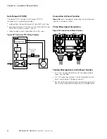
Figure 20. Terminal Block Layout
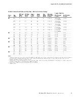
Table 24. I/O Specifications
Item
Specification
Analog Input 1
Selectable for either Voltage or Current reference signal
0 to 10V, 0 (4) to 20 mA; Ri – 250 ohm differential
Analog Input 2
Selectable for either Voltage or Current reference signal
0 to 10V, –10 to 10V, 0 (4) to 20 mA; Ri – 250 ohm differential
Digital inputs (8)
Positive or negative logic; 18 to 30 Vdc, one input can be used as thermistor input
+24V output
Auxiliary Voltage, +24V ±15%, total max. 250 mA on board (include optional cards)
+10 VREF
Output Reference Voltage, +10V +3%, max. load 10 mA
Analog Outputs
0 (4) to 20 mA; RL max. 500 ohm
0 to 10V, 10 mA
Digital Output
Open collector output, 50 mA/48V for CE, 50 mA/36V for UL
Relay Outputs (3)
Programmable relay outputs: 2 x Form C (Relay 1 and Relay 2) and 1 x Form A (Relay 3),
Relay 3 can be used as thermistor output
Switching capacity: 24 Vdc/6A, 48 Vdc/2A, 240 Vac/6A, 125 Vdc/0.4A
Содержание PowerXL DG1-32011FB-C21C
Страница 1: ...PowerXL DG1 Series VFD Installation Manual Effective March 2014 New Information ...
Страница 2: ......
Страница 83: ......