


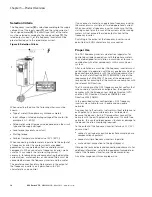


Chapter 5—Motor and Application
22
DG1 Series VFD
MN040002EN—March 2014
www.eaton.com
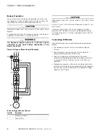
Bypass Operation
If you want to have the option of operating the motor with
the frequency inverter or directly from the input supply, the
input branches must be interlocked mechanically.
CAUTION
Debounced inputs may not be used in the safety circuit
diagram.
A changeover between the frequency inverter and the input
supply must take place in a voltage-free state.
WARNING
The frequency inverter outputs (U, V, W) must not be
connected to the input voltage (destruction of the
device, risk of fire).
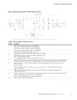
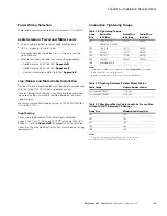
Figure 15. Bypass Motor Control (Example)
Table 16. Bypass Motor Control
CAUTION
Debounced inputs may not be used in the safety circuit
diagram.
Switch S1 must switch only when frequency inverter T1 is at
zero current.
Contactors and switches (S1) in the frequency inverter
output and for the direct start must be designed based on
utilization category AC-3 for the rated operational current of
the motor.
Connecting EX Motors
Note the following when connecting explosion-protected
motors:
●
The frequency inverter must be installed outside the
EX area.
●
Note the branch- and country-specific standards for
explosion-protected areas (ATEX 100a).
●
Note the standards and information of the motor
manufacturer regarding operation on frequency inverters—
for example, if motor reactors or sine-wave filters are
specified.
●
Temperature monitors in the motor windings (thermistor,
thermo-Click) are not to be connected directly to frequency
inverters but must be connected via an approved trigger
apparatus for EX areas.
Item No.
Description
1
Input/bypass contactor
2
Output contactor
Q1
I> I>
I>
Q11
S1
M1
T1
M
3~
L1 L2 L3
L1 L2 L3
U V W
Содержание PowerXL DG1-32011FB-C21C
Страница 1: ...PowerXL DG1 Series VFD Installation Manual Effective March 2014 New Information ...
Страница 2: ......
Страница 83: ......


