Eaton 9355 Tie Cabinet (20/30 kVA) Installation Guide
S
164201630 Rev D
www.eaton.com/powerquality
19
Chapter 4
Installing Options
This section describes the Powerware Hot Sync
®
CAN Bridge Card.
For other options, such as additional X-Slot
®
cards, power management software,
remote emergency power-off (REPO), relay output contacts, or programmable signal
inputs, refer to the
Eaton 9355 UPS (20/30 kVA) Installation and Operation Manual
.
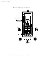
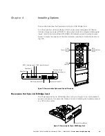
Figure 12 shows the location of the communication options and control terminals on
the UPS.
DB-9 Communication Port
REPO (normally open)
Signal Input 2
Signal Input 1
X-Slot
Communication
Bay #2
X-Slot
Communication
Bay #1
Relay Output Contacts
Control
Terminals
REPO (normally closed)
Pull-Chain Output
Contacts (parallel only)
Figure 12. Communication Options and Control Terminals
Powerware Hot Sync
®
CAN Bridge Card
The Powerware Hot Sync
®
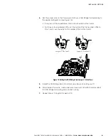
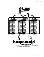
CAN Bridge Card, shown in Figure 13, can be installed to
provide connectivity for operational mode control and metering of a parallel system at
any UPS in the system.
Plug-in Terminal Block
Figure 13. Powerware Hot Sync
®
CAN Bridge Card

