Page 12
9130 UPS-EN
3. Power cables connection & Startup
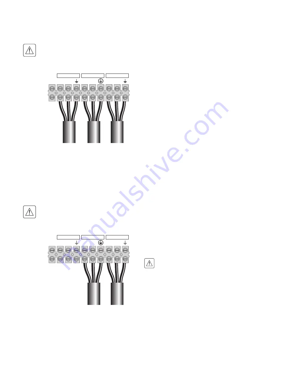
3.3 Separate input sources connection
This type of connection must be carried out by qualified electrical personnel.
Before carrying out any connection, check that the upstream protection device Input source is
open ("O") (OFF).
Always connect the earthing wire first.
JP L
N
L
N
L
N
BYPASS
INPUT
OUTPUT
1
- Remove the metal jumper (
see figure 18
).
2
- Insert the Input source cable through the cable
gland.
3
- Connect the 3 cables to the Input terminal block.
4
- Insert the Bypass source cable through the cable
gland.
5
- Connect the 3 cables to the Bypass terminal
block.
6
- Insert the Output cable through the cable gland.
7
- Connect the 3 cables to the output terminal
block.
8
- Put back and secure the terminal block cover
with the 2 screws.
9
- Tightened the cable glands.
Figure 18.
3.4
Frequency converter connection
This type of connection must be carried out by qualified electrical personnel.
Before carrying out any connection, check that the upstream protection device Input source is
open ("O") (OFF).
Always connect the earthing wire first.
JP L
N
L
N
L
N
BYPASS
INPUT
OUTPUT
1
- Remove the metal jumper (
see figure 19
).
2
- Insert the Input source cable through the cable
gland.
Do not connect anything to the Bypass
terminal block.
3
- Connect the 3 cables to the Input terminal block.
4
- Insert the Output cable through the cable gland.
5
- Connect the 3 cables to the output terminal
block.
6
- Put back and secure the terminal block cover
with the 2 screws.
7
- Tightened the cable glands.
Figure 19.


