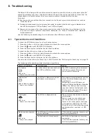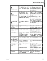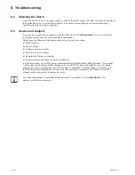
Page 23
9130 UPS-EN
ENGLISH
5. Communication
The RPO circuit is an IEC 60950 safety extra low voltage (SELV) circuit. This circuit must be
separated from any hazardous voltage circuits by reinforced insulation.
The RPO must not be connected to any utility connected circuits. Reinforced insulation to the
l
utility is required. The RPO switch must have a minimum rating of 24 Vdc and 20 mA and be
a dedicated latching-type switch not tied into any other circuit. The RPO signal must remain
active for at least 250 ms for proper operation.
To ensure the UPS stops supplying power to the load during any mode of operation, the input
l
power must be disconnected from the UPS when the remote power-off function is activated.
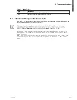
Table 9. RPO connections
RPO Connections
Wire Function
Terminal Wire Size Rating
Suggested Wire Size
RPO
L1
4–0.32 mm² (12–22 AWG)
0.82 mm² (18 AWG)
L2
Leave the RPO connector installed in the RPO port on the UPS even if the RPO function is not
needed.
Remote control connection and test
(
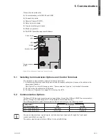
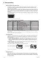
see figure 21
on page 21 for RPO location.)
1
- Check the UPS is shut down and the electrical supply network disconnected.
2
- Remove RPO connector from the UPS by unfitting the screws.
3
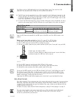
- Connect a normally closed volt-free contact between the two pins of connector, see picture 24.
+ -
Contact open: shut down of UPS
To return to normal operation, deactivate the external remote shut down
contact and restart the UPS from the front panel.
Figure 24.
4
- Plug the RPO connector into the back of the UPS and fix the screws.
5
- Connect and restart the UPS according to the previously described procedures.
6
- Activate the external remote shut down contact to test the function.
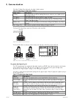
You can set the RPO polarity. See the "RPO Input Polarity" setting in "User Settings" on page 15.
Depending on user configuration, the pins must be shorted or open to keep the UPS running.
To restart the UPS, reconnect (re-open) the RPO connector pins and turn on the UPS manually.
Maximum resistance in the shorted loop is 10 ohm.
Always test the RPO function before applying your critical load to avoid accidental load loss.
Relay Output Contacts
The UPS incorporates three programmable relay outputs with potential free contacts for remote alarm
indications: a standard relay port and two outputs in the RS 232 communication port. See figure 21
on page 21 for the locations of the ports. An additional four relay outputs can be obtained with the
compatible Relay Interface Card.
Configure the relay outputs with the "Relay Configuration" setting in "User Settings" on page 15.
The relay output contacts must not be connected to any utility connected circuits. Reinforced
insulation to the utility is required. The relay output contacts have a maximum rating of
30 Vac/1A and 60 Vdc/2A nominal values.
RPO
Polarity


