


Eaton Power Xpert 9395 UPS Installation and Operation Manual 164201716—Rev 13
185
C
Chhaapptteerr 88 C
Coom
mm
muunniiccaattiioonn
This chapter describes the communication features of the Power Xpert 9395 UPS and provides information
about connecting hardware and using Terminal mode. For terminal wiring information, see paragraph
UPS System Interface Wiring Preparation
and paragraph
Installing Interface Connections
. For location
of the customer interface panels and terminals, see
and
through
.
88..11
X
X--S
Slloott C
Caarrddss
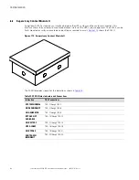
The Power Xpert 9395 UPS has four standard, factory-installed X-Slot communication bays. See
for
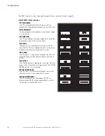
bay locations. The UPS is compatible with the following X-Slot cards (see
•
Power Xpert
®
Gateway Card - provides a data gateway from the UPS to the Power Xpert software;
provides remote monitoring through a Web browser interface, e-mail, and a network management system
using SNMP; connects to a twisted-pair Ethernet (10/100BaseT) network. Modbus TCP support provides
direct integration of the UPS parameters to a Building Management System (BMS). It has a built-in
switching hub that allows one additional network device to be connected to the network without the
requirement of an additional network drop.
•
Modbus Card - provides direct integration of UPS information (meters and status) to a Building
Management System (BMS) using the Modbus RTU protocol.
•
Relay Interface Card (AS/400). has isolated dry contact (Form-C) relay outputs for UPS status: Utility failure,
Low battery, UPS alarm/OK, or On bypass when interfacing with IBM AS/400 computers, other relay
connected computers, and industrial applications.
•
Industrial Relay Card (IRC) - indicates the operating status of the UPS system using the customer's
monitoring equipment. The IRC uses four isolated normally-open or normally-closed dry relay contacts to
indicate the UPS status. Online, Bypass, Battery, and Alarm modes can be monitored.
•
Powerware Hot Sync CAN Bridge Card - provides connectivity for operational mode control and metering
of a parallel system at any UPM in the system. In addition, this card can be used to connect optional
system monitoring devices, such as a Remote Monitor Panel II (RMP II), a Relay Interface Module II (RIM
II), or a Supervisory Contact Module II (SCM II) to the UPS. LAN drops for use with X-Slot connectivity
cards must be provided by facility planners or the customer.
LAN and telephone drops for use with X-Slot connectivity cards must be provided by facility planners or the
customer.
For installation and setup of an X-Slot card, contact an Eaton service representative (see section
). Refer to the manual supplied with the X-Slot card for user instructions.
Figure 110. Optional X-Slot Cards
Relay Interface Card
Modbus Card
Powerware Hot Sync
CAN Bridge Card
Industrial Relay Card
Power Xpert Gateway Card
Содержание Power Xpert 9395 550
Страница 1: ...p n 164201716 Revision 13 225 550 kVA Installation and Operation Manual Power Xpert 9395 550 275 UPS...
Страница 8: ......
Страница 18: ...xviii Eaton Power Xpert 9395 UPS Installation and Operation Manual 164201716 Rev 13 List of Figures...
Страница 31: ...10 Eaton Power Xpert 9395 UPS Installation and Operation Manual 164201716 Rev 13 Introduction...
Страница 35: ...14 Eaton Power Xpert 9395 UPS Installation and Operation Manual 164201716 Rev 13 Safety Warnings...
Страница 133: ...112 Eaton Power Xpert 9395 UPS Installation and Operation Manual 164201716 Rev 13 Understanding UPS Operation...
Страница 220: ...Eaton Power Xpert 9395 UPS Installation and Operation Manual 164201716 Rev 13 199 Product Specifications...
Страница 221: ...16420171613 164201716 13...


