background image

9

Instructional Booklet 

IB02102006E

Effective May 2011

Type MVS (previously WLI)

metal-enclosed switchgear—

4.76 kV, 15.0 kV, 27.0 kV, and 38.0 kV

eaton corporation

 www.eaton.com

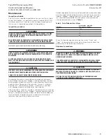
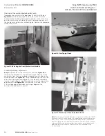
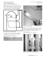
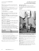
Figure 10. Top Cable Entrance (Energy Source), Front Access

Figure 11. Bottom Cable Entrance (Energy Source), Front Access

Содержание MVS

Страница 1: ...r operation 23 Electromechanical stored energy release shunt trip 25 MVS switchgear bolt tightness for bus connections and connections to switch terminal pads 28 Common renewal parts 28 Effective May...

Страница 2: ...ovide safe economical switching and circuit protection where infrequent disconnecting means is required Switchgear identification A nameplate is located inside the small access door of each type MVS s...

Страница 3: ...ility is provided for padlocking the switch in the Open or Closed position 5 Facilities are provided for padlocking the door handles closed 6 Mechanical indicators show whether the switch mechanism is...

Страница 4: ...upon receipt of the switchgear and before removing it from the truck Shipping papers should be checked to be sure that all boxes or other accompanying pieces have been received If any damage or short...

Страница 5: ...ght bolts removed from one side sheet in Step 1 Figure 3 Joining MVS Enclosures Step 4 Make the main and ground bus connections using splice plates and the hardware furnished The busbar is tin or silv...

Страница 6: ...tory pre cut to the proper length The installer MUST cut them to fit Factory cables are unshielded For 15 kV 27kV and 38 kV applications they must be properly separated from each other from all ground...

Страница 7: ...ign of MVS switchgear is based upon use of pre formed type electrical stress relief devices such as 3 M Quickterm IIT RaychemT heat shrink termination systems etc The stress relief devices are to be p...

Страница 8: ...witchgear 4 76 kV 15 0 kV 27 0 kV and 38 0 kV eaton corporation www eaton com Figure 6 Bottom Cable Entrance Energy Source Rear Access Figure 7 Top Cable Entrance Energy Source Rear Access Figure 8 Un...

Страница 9: ...e May 2011 Type MVS previously WLI metal enclosed switchgear 4 76 kV 15 0 kV 27 0 kV and 38 0 kV eaton corporation www eaton com Figure 10 Top Cable Entrance Energy Source Front Access Figure 11 Botto...

Страница 10: ...witchgear 4 76 kV 15 0 kV 27 0 kV and 38 0 kV eaton corporation www eaton com Figure 12 Unfused Top Cable Exit to Load Front Access Figure 13 Unfused Bottom Cable Exit to Load Front Access Figure 14 F...

Страница 11: ...to an exposed conductor prior to insulating WARNING the USE OF SOLVENTS OILS JOINT COMPOUNDS OR GREASE ON OR NEAR NORYL INSULATION WILL DESTROY IT 1 1 2 Minimum Lap Filler Pre Insulation Typical Insul...

Страница 12: ...with distilled water Do not use any abrasives or solvents Step 2 Apply the filler over the bare conductor and hardware to cover and to smooth out the surface Blend the contour into pre insulation sur...

Страница 13: ...m in 914 4 mm Left to right front to rear and diagonally as measured by a laser level at any point beneath the switchgear assembly 44 11 0 Type 6 00 152 0 Minimum 86 22 0 Type 1 37 35 0 Type 1 00 25 0...

Страница 14: ...red by a laser level at any point beneath the switchgear assembly 5 81 148 0 Type 5 81 148 0 Type 6 00 152 0 Minimum 1 28 33 0 Type 1 00 25 0 Minimum Minimum Front Door 30 00 762 0 Minimum 2 12 54 0 T...

Страница 15: ...h terminal pad 2 To the bus support insulator mounted in the superstructure Use the bolts provided to secure the bus sections Step 2 Units with a main bus also require horizontal bus sections bolted t...

Страница 16: ...le because it is not rigidly connected to the blades Therefore the switch can be safely closed under short circuit conditions within its fault close rating Mechanism Cover Door Switch Shaft Interlock...

Страница 17: ...or weak ened insulation Remove dust from barriers live parts insulators drive rod links and enclosure surfaces If necessary wipe clean with isopropyl alcohol or distilled water then wipe dry After th...

Страница 18: ...ng switch mechanism from the top the bottom stop bolt and nut adjusts the closed position see Figure 25 In the closed position the shaft rod ends should be slightly over toggle This can be easily chec...

Страница 19: ...sition the clearance between the edge of the main blade and the break jaw should be as listed in Table 4 see Figure 27 The top stop bolt adjusts this dimension Table 4 Main Blade to Break Jaw Clearanc...

Страница 20: ...op nut must be removed then a sensitive torque wrench used to set the proper contact pressure as given in Table 5 Table 5 Necessary Contact Pressure Fault Close Rating kA Asymmetrical Torque in lb Nm...

Страница 21: ...justment Main spring replacement Step 1 To disengage the main spring remove the switch mechanism cover see Figure 23 Step 2 Take a 5 16 18 threaded rod 4 00 inches 101 6 mm long and screw it into the...

Страница 22: ...nsulation In general the switch requires only moderate lubrication All excess lubrication must be removed with a clean cloth to prevent any accumulation of dust or dirt Avoid getting any lubrication o...

Страница 23: ...ing personnel Line LO LO LD LD Load Line Motor operation Motor operated MVS switch The motor operated MVS switch is essentially a standard manually operated switch with a motor driven linear actuator...

Страница 24: ...and remove this pin see Figure 32 Remove the bottom support pin holding the linear actuator pull it out sufficiently to permit unplugging the linear actuator and removing it see Figure 33 The switch...

Страница 25: ...he switch operating handle will result in damage to the switch If the switch status nameplate indicates that the spring is charged the trigger latch must be released to change the position of the swit...

Страница 26: ...ger Coil Hand Trip Lever Trigger Latch Teeter Assembly Trip Link Spring Rod Spring Main Lever Pinned to Main Shaft Main Lever Stop Angle Assembly Main Shaft Spring Rod Pin Spring Lever Figure 37 Switc...

Страница 27: ...th Replace the shaft blocking assembly before energizing Blade and arc chute alignment The blade and arc chute alignment procedures are the same for the standard MVS switch described in the Maintenanc...

Страница 28: ...it glass polyester 27 38 kV 1 7278A27G12 Contact grease 2 oz jar As required 7274A48H02 Mechanism grease 1 lb container As required 53701AI02E Auxiliary switch assembly kit 1 221C395G01 4 76 15 kV MVS...

Отзывы: