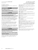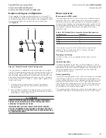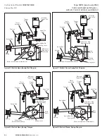
20
Instructional Booklet
IB02102006E
Effective May 2011
Type MVS (previously WLI)
metal-enclosed switchgear—
4.76 kV, 15.0 kV, 27.0 kV, and 38.0 kV
eaton corporation
www.eaton.com
Step 1e:
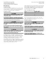
Loosen the four hinge bolts and the two break jaw bolts .
Insert the removable handle in the maintenance hub on the shaft
and “Close” the switch .
otee:
N
For safety purposes, the switch will not fully “Close” and will revert to
the “Open” position if pressure on the handle is released .
Step 2e:
Hold the switch in the “Closed” position with the handle
and tighten the bolts on both the hinge and jaw per the torque
specifications given on
page 28
.
Arc chute alignment
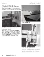
For the following procedure, refer to
Figure 28
.
Step 1e:
Loosen the two arc chute mounting bolts . Adjust the arc
chute so that its opening is parallel to the main blade then lightly
tighten the mounting bolts .
Step 2e:
Using the blade alignment hub, slowly close the switch
and check that the flicker blade is in line with the arc chute opening .
If necessary, move the arc chute left or right until it lines up with
the flicker blade .
Step 3e:
Tighten the arc chute mounting bolts and recheck
the alignment .
Vertical position of break jaw
Step 1e:
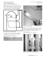
Close the switch . Check that the upper spacers of the main
blades are 0 .1875 ± 0 .0625 inches (4 .76 ± 1 .59 mm) above the tops
of the break jaws (see
Figure 22
) .
Step 2e:
If they are not, loosen the bolts holding the break jaw and
adjust as necessary . When the setting is correct, tighten bolts to
proper torque value (see
page 28
) .
Break jaw bolt and hinge contact bolt tightness
The disk springs on the main blade assembly must provide the
necessary contact pressure between the main blades and stationary
mating parts when the switch is “Closed .” At the break jaw end,
the elastic stop nut must be removed, then a sensitive torque
wrench used to set the proper contact pressure as given in
Table 5
.
Table 5. Necessary Contact Pressure
Fault-close rating,
ka asymmetrical
torque
in-lb (nm)
40
20 (2.260)
61
25 (2.825)
For the hinge end, there are two configurations:
1.
If there is only an elastic stop nut installed, tighten it to 25 ft-lb
(33 .90 Nm), and then back off the nut one full turn .
2.
If there is an elastic stop nut that jambs a standard hex nut,
remove the elastic stop nut, tighten the standard hex nut to
20 ft-lb (27 .12 Nm), then back off one full turn . Reinstall the
locking nut and jamb it against the standard hex nut, being
careful not to turn either the bolt or the standard nut .
otee:
N
Standard ohm readings between the top terminal pad and the bottom
terminal pad on each pole are not to exceed 60 micro ohms .
Replacement procedures
Main blade subassembly and break jaw replacement
The switch should be in the “Closed” position . Disconnect the drive
rod link from the main blade assembly by removing the clevis pins
(see
Figure 27
) .
Method A
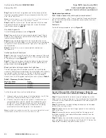
For the following procedure, refer to
Figure 29
.
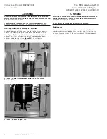
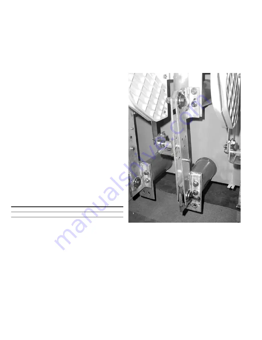
Figure 29. Main and Flicker Blade Replacement. Notice the
Hinge Bolt Is Pulled Out to Indicate the Method of Replacement
Step 1e:
Remove the bolt and elastic stop nut holding the switch
blades to the stationary hinge parts . The main blade and flicker blade
assembly are now freed and may be removed . The terminal pad will
remain in place .
Step 2e:
Remove the two bolts holding the break jaw to the upper
terminal . The jaw is now free .
Step 3e:
Replace the jaw, but only finger tighten its two mounting
bolts at this time .
Step 4e:
Remove the contact pressure bolt on the hinge end of
the blade assembly, then separate the blade assembly from the
stationary hinge parts .
Step 5e:
Replace the main blade assembly on the stationary hinge
parts and tighten the elastic stop nut to 20 ft-lbs (27 .12 Nm) on the
hinge end of the blade, then back off one full turn .


