


About the Display/Operator
System
8
09/10 MN05013011Z-EN
Key to part numbers
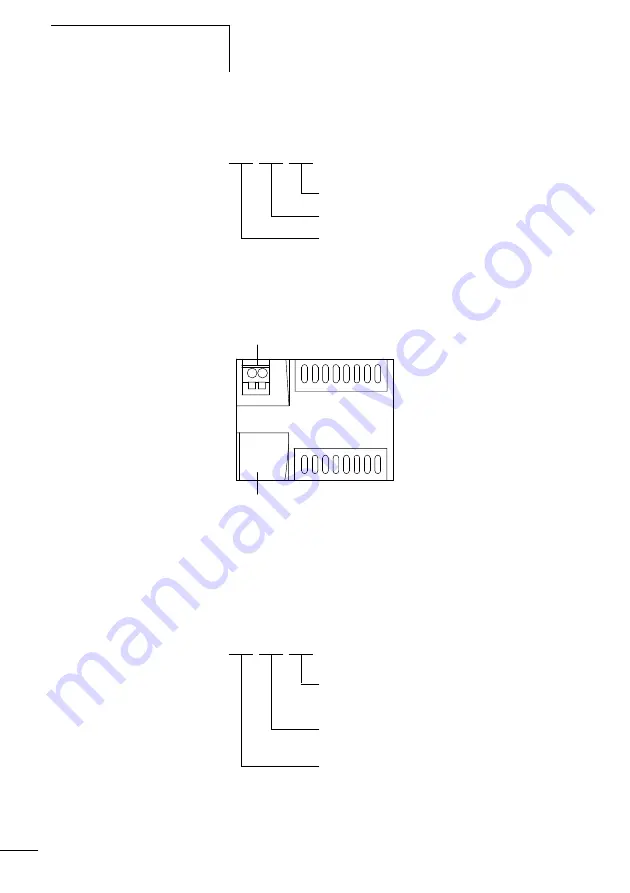
Power supply unit/communication module
Figure 3:
Power supply unit/communication module
a
Supply voltage
b
Serial interface for point-to-point connection
Key to part numbers
MFD - 80 - B
B = with buttons
with display
Multi-function display
MFD - CP4 - XXX
500 = For connection to easy500 and easy700
800 = For connection to easy800
CP4 = Power supply/central processing unit
Multi-function display
a
b


