44
INSTALLATION AND OPERATION MANUAL
25-16383-B August 2019 www.eaton.com
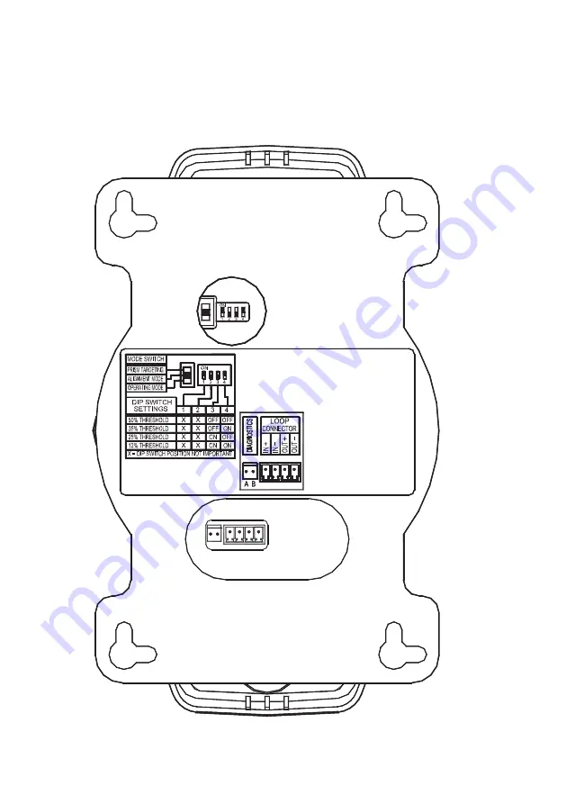
9. Installazione - Montaggio - Configurazione del Rivelatore Interfaccia
9. Installazione - Montaggio - Configurazione del Rivelatore
Interfaccia
Figure 4.
Fig. 4.
Страница 1: ...ligent Addressable Beam Detectors Linienf rmiger optischer Rauchmelder Rivelatori lineari Installation and Operation Manual Installations und Bedienungsanleitung Manuale di installazione e uso 13 0786...
Страница 2: ...0 4 2 Prism installation 11 5 PRISM TARGETING MODE 11 6 ALIGNMENT MODE 11 6 1 Enabling alignment mode 12 6 2 Adjustment in alignment mode 12 6 3 Alignment process flow diagram 13 6 4 Exiting alignment...
Страница 3: ...4 2 Montage des Prismen Reflektors 25 5 MELDER AUSRICHTEN REFLEKTOR ANVISIEREN 25 6 1 Umschalten in den Abgleich Modus 26 6 2 Justage im Abgleich Modus 26 6 3 Abgleich Proze im Flu diagramm 27 6 4 Abs...
Страница 4: ...PRISMA 38 6 MODULO DI ALLINEAMENTO 39 6 1 Attivazione del Modulo di Allineamento 39 6 2 Modulo di Allineamento 39 6 3 Diagramma del Processo di Allineamento Corrente 40 6 4 Uscita dal Modulo di Alline...
Страница 5: ...ed Sale of the product shown in this literature is subject to the terms and conditions outlined in appropriate Eaton selling policies or other contractual agreement between Eaton and the purchaser THE...
Страница 6: ...should contact your local distributor for product pricing availability ordering expediting and repairs Website Use the Eaton website to find product information You can also find information on local...
Страница 7: ...ed signal reduces to below the selected threshold and is present for approximately 10 seconds a Fire condition is activated The Fire condition will automatically reset after 10 seconds once the beam s...
Страница 8: ...s positioning may need to be adjusted This is to allow for a beam path clearance radius of 0 5 metres The maximum distance either side of the beam axis is found to be typically 7 5 metres for satisfac...
Страница 9: ...tres either side of the beam 8 to 8 7 5 7 5 x 20 100 metres 8 9 metres Therefore with a roof pitch of 20 degrees the lateral coverage can be increased from 7 5 metres either side of the beam to 9 metr...
Страница 10: ...r installation If switches 3 and 4 require resetting after installation a power down reset is required entering into Alignment Mode can also be used as a reset 4 1 Detector head assembly installation...
Страница 11: ...Do not remove the detector from the wall during this action Using the mode switch See fig 4 select Prism Targeting Mode Switch will be in the up position At this time there may be a fault condition sh...
Страница 12: ...ng too much signal and is attempting to reduce the infrared power output to compensate Wait at this point until the indicator lamp is OFF this may take up to 20 seconds depending on the distance betwe...
Страница 13: ...n of the thumbwheel Exit Alignment Mode and enter the Operating Mode LED flashing Slowly adjust a thumbwheel in one direction and observe the LED s LED flashing For optimum alignment deflection of the...
Страница 14: ...require testing for both alarm and fault conditions 7 1 Alarm smoke test Taking note of the threshold selected during installation default 35 Select obscuration mark on filter to correspond with the...
Страница 15: ...gh the back plate of the Detector Head See Fig 4 The small 2 pin connector on the left is not used 8 2 DIP Switch settings Access to the configuration settings is through the back plate of the Detecto...
Страница 16: ...nd configuration settings 8 3 Typical single zone wiring MAB50R MAB100R Connections Fire Panel Connections Loop Start 2 core screen cable to next device in Loop Loop IN Loop OUT Loop Finish From last...
Страница 17: ...17 INSTALLATION AND OPERATION MANUAL 25 16383 B August 2019 www eaton com 9 Detector interface assembly configuration settings 9 Detector interface assembly configuration settings Figure 4 Fig 4...
Страница 18: ...a reflective beam can be used As a general rule of thumb there should be at least 0 5m diameter clearance down the entire beam path If there are highly reflective objects within 1 metre diameter of th...
Страница 19: ...isolators 700mA max Isolator Resistance in closed state 0 13 max Leakage Current into direct short circuit isolator open 13mA max Parallel Fault Resistance to be seen at the Control Panel for isolator...
Страница 20: ...pfindlich ber 35 bis 50 unempfindlich Die h chstempfindliche Einstellung von 12 sollte nur in Sonderf llen verwendet werden Sinkt das empfangene Signal unter den gew hlten Wert ununterbrochen f r die...
Страница 21: ...Ein gut plazierter Melder garantiert schnellstes Ansprechen und Ausl sen Versuche haben gezeigt Rauch steigt selten direkt und gerade zur Decke auf Luftwirbel und unterschiedliche Luft Temperatur Schi...
Страница 22: ...stand 0 3 bis 0 9 m bei flachen D chern H he bis 16m Es gelten folgende Mindestabst nde f r die Melderachsen Es sind die geltenden nationalen Vorschriften f r die Projektierung von Brandmeldesystemen...
Страница 23: ...te seitliche berwachungs bereich in Relation zum Dachneigungswinkel vergr ert werden max bis 25 Neigung Beispiel Die Dachneigung betr gt 20 und der berwachungsbereich Y vergr ert sich auf beiden Seite...
Страница 24: ...onen ALARM speichern oder AUTO Reset werksseitig eingestellt ist die Funktion AUTO Reset siehe Fig 4 Hinweis In Deutschland w hlt man f r BMA s meistens ALARM gespeichert und f r RWA s AUTO Reset bei...
Страница 25: ...rahl muss rechtwinklig auf den Reflektor treffen von dem er auf demselben Wege wieder zur ckgespiegelt wird Der Kernstrahl Weg mu frei bleiben bewegte Teile d rfen ihn weder ganz noch teilweise blocki...
Страница 26: ...ieren Sie den Reflektor so da die gelbe LED dauernd leuchtet 6 Abgleichen des Melders Fein Abgleich Den Melder richtet man exakt mit den beiden R ndelschrauben hoch runter rechts links auf den Reflekt...
Страница 27: ...n Schalter Mitte Abgleich Modus LED gelb leuchtet ca 5 Sekunden Welche LED leuchtet auf R ndelschraube langsam in eine Richtung drehen und Status LEDs beobachten R ndelschraube nicht weiter drehen und...
Страница 28: ...ht die LED gelb und das St rmelde Relais wird angezogen der Rauchmelder ist in Betrieb Im ordnungsgem en Betrieb blinkt die LED gelb alle 10 Sekunden 7 System Test Vor der endg ltigen Inbetriebnahme s...
Страница 29: ...s Melderkopfs zug nglich siehe Abb 4 Der kleine 2 Stifte Stecker auf der linken Seite wird nicht verwendet 8 2 DIP Schalter Einstellungen Zugriff auf die Konfigurationseinstellungen erfolgt ber die R...
Страница 30: ...lkreis Anschl sse f r MAB50R MAB100R Anschl sse zur Brandzentrale Regelkreis Anfang 2 Drahtkabel Abschirmung an n chstes Ger t im Regelkreis Regelkreis eingang Regelkreis Abschluss Vom letzten Ger t i...
Страница 31: ...31 INSTALLATION AND OPERATION MANUAL 25 16383 B August 2019 www eaton com 9 Ansicht Anschlusse und Konfigurationsschalter 9 Ansicht Anschlusse und Konfigurationsschalter Figure 4 Fig 4...
Страница 32: ...lder eingesetzt werden kann Als Daumenregel sollte zumindest ein Abstand von 0 5 m Durchmesser entlang des gesamten Lichtstrahls vorhanden sein Befinden sich hochspiegelnde Gegenst nde innerhalb von 1...
Страница 33: ...700mA max Trennschalterwiderstand in schlossenem Zustand 0 13 max Verluststrom im offenen Kurzschluss Trennschalter 13mA max An Schalttafel sichtbarer Parallelfehler Widerstand zum ffnen der Trennsch...
Страница 34: ...di sotto della soglia selezionata ed e per circa 10 secondi una condizione di Incendio viene attivata La condizione di Incendio si ripristinera automaticamente dopo 10 secondi una volta che il segnale...
Страница 35: ...o che potrebbero oscorare la traiettoria la posizione del rivelatore prisma i potrebbe necessitare di regolatazione Questo permette una traiettoria del rivelatore in un raggio di 5 metri La distanza m...
Страница 36: ...del ricevitore 8 8 7 5 7 5 x 20 100 metri 8 9 metri Quindi con un tetto inclinato di 20 gradi la copertura laterale puo essere aumentata da 7 5 metri per entrambi i lati della barriera lineare a 9 met...
Страница 37: ...essere cambiata dopo l installazione viene poi richiesto il regolamento della corrente inserire il Modulo Allineamento che puo anche essere usato come un riazzeramento 4 1 Montaggio ed Installazione...
Страница 38: ...rdo pre carica di 5 secondi dopo che la corrente viene applicata per permettere ai circuiti interni di stabilizzarsi correttamente Non rimuovere il rivelatore dal muro durante questa azione Usando il...
Страница 39: ...i allineamento e indicato dal colore e dalla disposizione della lampada del ricevitore sulla parte anteriore del Rivelatore LAMPEGGIO ROSSO Il Rivelatore riceve troppo segnale e cerca di ridurre l ene...
Страница 40: ...re dal Modulo Allineamento ed entrare nel Modulo Operativo Lentamente regolare un rotella in una direzione e osservare che i LED smettino di lampeggiare LED lampeggia Per l allineamento ottimale la de...
Страница 41: ...ondizioni di allarme e di guasto richiederanno una verifica 7 1 Test Allarme fumo Prendere nota della soglia selezionata durante l installazione parametro preassegnato 35 Selezionare il segnale di osc...
Страница 42: ...o della Parte Alta del Rivelatore Vedi Fig 4 La morsetta sulla destra non e usata 8 2 DIP Switch Installazione L accesso all installazione della configurazione e attraverso la parte posteriore del dis...
Страница 43: ...ssione e Configurazione 8 3 Zona tipica di collegamento singolo MAB50R MAB100R Connections Fire Panel Connections Loop Start 2 core screen cable to next device in Loop Loop IN Loop OUT Loop Finish Fro...
Страница 44: ...ION AND OPERATION MANUAL 25 16383 B August 2019 www eaton com 9 Installazione Montaggio Configurazione del Rivelatore Interfaccia 9 Installazione Montaggio Configurazione del Rivelatore Interfaccia Fi...
Страница 45: ...rivelatore lineare E meglio che ci sia almeno 0 5m di diametro di compensazione lungo la traiettoria dell intera barriera lineare Se ci sono oggetti altamente riflessi entro 1 metro di diametro dalla...
Страница 46: ...ax Resistenza dell isolatore a riposo 0 13 max Corrente di corto circuito con isolatore aperto 13mA max Resistenza vista dalla centrale con optoisolatore aperto 200 12 Note di Servizio Applicazione Pe...
Страница 47: ...47 INSTALLATION AND OPERATION MANUAL 25 16383 B August 2019 www eaton com Notes Notes...
Страница 48: ...303220 Firesales eaton com Firetechsupport eaton com Eaton Electrical Systems Ltd Wheatley Hall Road Doncaster DN2 4NB TEL 44 0 1302 303303 FAX 44 0 1302 367155 2019 Eaton All Rights Reserved Eaton is...