Instruction Manual
MN013010EN
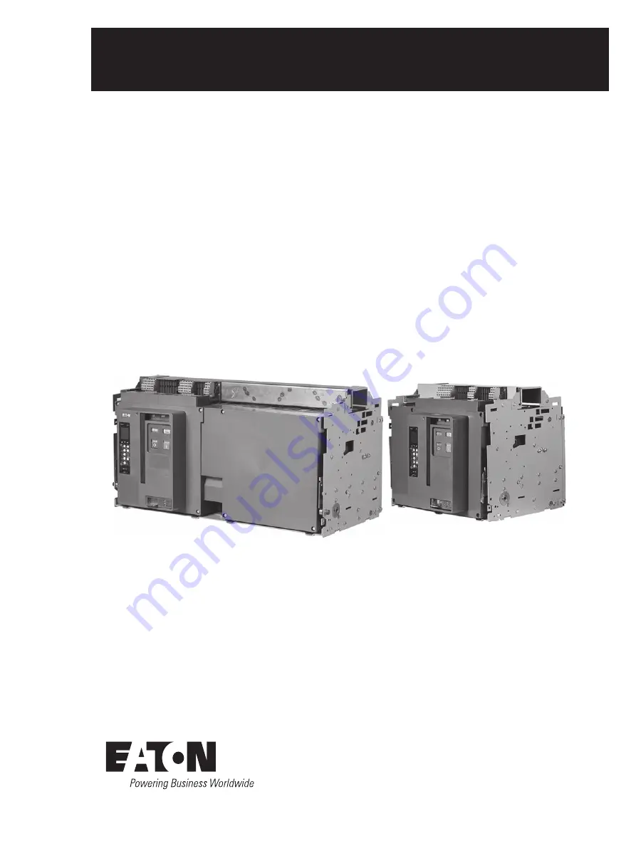
New generation IZM97, 99 low voltage air circuit breaker instruction manual
IZM97
IZM99
Страница 1: ...Instruction Manual MN013010EN New generation IZM97 99 low voltage air circuit breaker instruction manual IZM97 IZM99...
Страница 2: ...s specific to the trip units For application information consult Eaton or see applica ble Product Guides Technical Documents and Industry Standards Safety All safety codes safety standards and or regu...
Страница 3: ...6 2 Installing secondary jumpers 5 2 7 Installing drawout circuit breaker 6 2 7 1 Circuit breaker positioning 6 2 7 2 Levering circuit breaker 8 2 8 Fixed circuit breaker 11 2 9 Circuit breaker operat...
Страница 4: ...Accessory installation 32 SECTION 5 DIMENSIONAL DRAWINGS 60 SECTION 6 PROTECTIVE CHARACTERISTIC CURVES 77 SECTION 7 WIRING DIAGRAMS 88 SECTION 8 INSPECTION AND MAINTENANCE 97 8 1 General 97 8 2 Gener...
Страница 5: ...operties excellent dielectric characteristics and arc tracking resistance The drawout IZM9 circuit breaker is a through the door design having three breaker positions with the compartment door closed...
Страница 6: ...ipment its operation and the associated haz ards should be permitted to work on the equipment Additionally only qualified personnel should be permit ted to install or operate the equipment 2 Always be...
Страница 7: ...protective packaging until the breakers are ready for inspection testing and or installation When ready to inspect and install the circuit breaker carefully remove the banding straps and lift off the...
Страница 8: ...ious damage The current rating of the rating plug installed in the trip unit should match the current rating of the sensors mounted on the lower primary stabs of the circuit breaker Check to make sure...
Страница 9: ...der CAUTION Do not disable rejection interlocks Doing so and using a lower capacity circuit breaker in an incompatible cassette could result in an electrical fault that could result in death bodily in...
Страница 10: ...down onto the extension rails Be certain that the circuit breaker s four molded dra wout rail supports are fully seated in the extension rail cut outs on both sides Figure 2 3 Do not remove the lifti...
Страница 11: ...f Compartment Primary Connections Not Made Only Ground Connection Made Breaker Still Behind Door Typical Storage Position Circuit Breaker Side View Compartment Front Door Secondary Connection Made Rea...
Страница 12: ...ndard 3 8 inch square drive and ratchet which is not provided Figure 2 9 As long as the levering access door is raised the circuit breaker is held trip free Begin by rotating the levering in screw to...
Страница 13: ...reaker including automatic primary and sec ondary connections For the IEC circuit breaker a cassette style using horizontal stabs and horizontal customer busbar terminals is available as standard Figu...
Страница 14: ...installation Figure 2 11 Drawout cassette features front and rear views 2 1 4 3 6 5 8 7 1 1 2 2 3 4 5 6 6 7 7 8 9 9 9 10 10 10 4 Front View Rear View Extension Rails Extension Rail Cutout Secondary P...
Страница 15: ...tible with the drawout circuit break er s type secondary connector Both secondary connection devices are mounted at the top front of the circuit breaker The fixed circuit breaker frame has two mountin...
Страница 16: ...00 2000 2000 2000 IZM97 2500A 2500 2500 2500 2500 2500 2500 IZM97 3200A 3200 3150 3100 3000 2800 2550 IZM99 4000A 4000 4000 4000 4000 4000 4000 IZM99 5000A 5000 5000 5000 5000 5000 5000 IZM99 6300A 63...
Страница 17: ...IZM97N3C 16 12 24 120 240 IZM97H3C 16 12 24 120 240 IZM97B3C 20 12 24 190 330 IZM97N3C 20 12 24 190 380 IZM97H3C 20 12 24 190 380 IZM97B3C 25 8 20 200 500 IZM97N3C 25 8 20 200 500 IZM97H3C 25 8 20 200...
Страница 18: ...out electrical clearance is intended to provide a guideline for the installation of fixed type or drawout type circuit breakers in an enclosure The diagram and related dimensions can be used for refer...
Страница 19: ...n to both configurations and will be discussed in this section The mounting features unique to the drawout and the fixed configurations will be covered individually in Sections 4 and 5 respectively Co...
Страница 20: ...7 6 2 5 8 10 11 5 2 1 4 3 6 7 8 9 10 11 Fixed primary terminal with optional vertical adapter Arc chamber Sensor rating viewing window Mounting foot Circuit breaker nameplate Tripper bar Baffled arc...
Страница 21: ...l double wide standard frame fixed circuit breaker features front and rear views 7 7 6 5 8 1 1 3 4 9 9 9 9 10 4 10 5 2 1 4 3 10 7 6 9 8 Arc chamber Mounting foot Circuit breaker nameplate Phase identi...
Страница 22: ...indicator Three accessory windows Trip unit Rating plug Contact status open close Spring status charged discharged Manual OFF button push Manual ON button push Manual charge handle Optional operation...
Страница 23: ...ing mechanism sits on the front of the case and is electrically isolated and insulated from current contact struc tures It is covered by an insulating front cover 3 3 Operating mechanism The IZM9 oper...
Страница 24: ...sily in the field For more details on these devices refer to Section 4 1 and 4 2 in this booklet An electrical operator that is used to charge the closing spring automatically can be added to a manual...
Страница 25: ...units Functions PXR 20 PXR 25 LSIG protection Yes Yes Disable I Yes Yes GF protection Option Option GF alarm Option Option Display Yes Yes Programmable No No Current metering Yes Yes Power energy met...
Страница 26: ...The In rating displayed on the LCD screen and In rating printed on the frame rating module battery cover MUST ALWAYS AGREE 3 4 5 Trip actuator The low energy trip actuator is a small electromagnetic d...
Страница 27: ...ustomer use is not required the circuit breaker is supplied with both plug in connectors male and female just described in the two previous paragraphs The plug in connectors are joined and attached to...
Страница 28: ...ctrical accessories Three can be viewed for identification by name and rating through view ing windows located in the right front of the circuit breaker Figure 4 1 All four are plug in type and can be...
Страница 29: ...wo versions of the LCS are available One version is wired internally to the shunt trip coil control circuit On the other version the LCS switch contacts are brought out through the secondary contacts...
Страница 30: ...ductive load A 250 Vac 125 Vdc 250 Vdc 10 0 5 0 25 Table 4 4 Auxiliary switch overcurrent trip switch and cell switch contact ratings Control voltages Operational voltage range 85 110 Dropout volts 30...
Страница 31: ...ndition Opening as a result of a circuit breaker s manual open button shunt trip or undervoltage release does not cause the overcurrent trip switch to operate The overcurrent trip switch has 2a 2b For...
Страница 32: ...circuit breaker in the OFF position It is mounted in the lower right portion of the circuit breaker and can be viewed through the front cover Figure 4 11 The customer supplies the key lock The provis...
Страница 33: ...connections to be made Figure 4 14 Figure 4 15 Cell switch drawout position indicator unmounted Figure 4 16 Cell switches mounted on cassette Figure 4 17 Door escutcheon and gasket Figure 4 13 Safety...
Страница 34: ...closure when others are closed A lever assembly is mounted on each breaker that interfaces with the pole shaft and the tripper bar The lever assemblies are interconnected with either cables or rods d...
Страница 35: ...upply B If B breaks circuit breaker A C can still turn off B can turn off only when A C breaks It requires 2 set of ropes ABC 000 100 010 001 101 32 type 3 circuit breakers 2 for normal power supply A...
Страница 36: ...s a mechanical device used to pro vide a record of the number of circuit operations It can be viewed through the breaker s front cover Required tools 1 4 inch socket wrench 10mm socket Phillips head s...
Страница 37: ...ention to the counter rocker position Figure 3 Step 3 Figure 5 Step 5 Figure 4 Step 4 Figure 6 Step 6 Step 4 Install the counter C onto the bracket A and fix it with M3 5x8 screws E Torque to 5 8in lb...
Страница 38: ...il is energized by a voltage signal To replace the shunt trip it is necessary to replace the shunt trip and disconnect switch at the same time Section 2 Installation of shunt trip Proceed with the fol...
Страница 39: ...jury or property damage Section 1 General information A spring release is recommended on electrically operated circuit breakers although it is an optional device It remotely closes the circuit breaker...
Страница 40: ...uld be switched to the OFF position and mechanism springs discharged Failure to follow these steps for all procedures described in this instruction leaflet could result in death bodily injury or prope...
Страница 41: ...afe work location 3 Drawout circuit breakers should be levered racked out to the DISCONNECT position 4 All circuit breakers should be switched to the OFF position and mechanism springs discharged Fail...
Страница 42: ...e 1 Terminal 50 60 2 Terminal 62 72 3 Terminal 74 84 Step 5 Re install the front cover by following the procedure in Step 1 Figure 1 Content of assemblies IZM9 low voltage circuit breaker latch check...
Страница 43: ...3 Insert the connector on the LCS into the circuit board of the closing coil and insert the LCS into the LCS slot on the additional bracket Make sure the LCS is fully installed Figure 5 Step 5 Step 4...
Страница 44: ...overs Adding a button cover with metal bezel can prevent all the operational access to the ON button Required tools 1 8 inch drill Tap wrench or tap drill Flat head screwdriver Kit Parts Identificatio...
Страница 45: ...the circuit breaker is leveled into the cassette the cell switch changes its sta tus The cell switch can be placed in one to three positions to display three states of the circuit breaker D T C As th...
Страница 46: ...to work on the equipment 2 Always de energize primary and secondary circuits if a circuit breaker cannot be removed to a safe work location 3 Drawout circuit breakers should be levered racked out to t...
Страница 47: ...circuit breaker front cover Remove the hexagonal mounting screws four for 3 pole breakers and six for 4 pole breakers from the front cover using a 10 mm 1 4 inch socket wrench Then pull down on the c...
Страница 48: ...the hole above the mounting nut on the mounting panel of the lock Step 7 Install the interlocking adapter kit F at the rear end of the key Step 8 Install the lock nut G at the rear end of the key loc...
Страница 49: ...ructions Step 15 Re install the front cover IZM9 low voltage circuit breaker Castell key inter lock kits WARNING 1 Only qualified electrical personnel should be permit ted to work on the equipment 2 A...
Страница 50: ...ng cable M Fixing pin M5x0 7 N Interlocking lever O Mounting lock screw 3 P Interlocking lever screw M3 5x10 Section 2 Installation of key interlock Proceed with the following 12 steps Step1 To remove...
Страница 51: ...tion when mounted to a lock panel Step 6 Install the interlocking cable L hexagonal bracket H and interlocking adapter D Connect and fasten them using the bracket screws K and connect screws J Step 7...
Страница 52: ...to a safe work location 3 Drawout circuit breakers should be levered racked out to the DISCONNECT position 4 All circuit breakers should be switched to the OFF position and mechanism springs discharge...
Страница 53: ...n be used to interlock two to three IZM circuit breakers Mechanism interlocking holds one or more circuit breakers tripped prevents closure An operating lever assembly is installed on each circuit bre...
Страница 54: ...t cover Step 2 Remove the separation block from the right side of the front cover using a plier to form a U shaped slot Note that the separation edges must not have burrs Step 3 Mount the drive arm E...
Страница 55: ...w and M6 self locking washer through the back panel and support bracket and interlock with the square nut to fas ten the back panel onto the support bracket Torque to 7 9Nm Figure 6 Step 4 Figure 7 St...
Страница 56: ...ose the circuit breaker and rotate the drive rod by approximately 60 degrees counterclockwise The clearance between the drive rod lower left corner and support bracket edge is 1 4mm refer to Figure 2...
Страница 57: ...ver assemblies are interconnected with cables Cables can be used for any orientation of the circuit breaker Required tools 10mm socket and 1 4 inch socket bar 10mm open end wrench 11 16 inch open end...
Страница 58: ...top parts from the circuit breaker Then insert a square nut F in the slot The plane of the nut should be placed outward Finally re tighten the three screws Step 4 Re install the front cover removed in...
Страница 59: ...d in Table 1 and Figure 8 Table 1 Cable routing connection indication Six groups of connection cables Outgoing end Incoming end 1A 1C 3D 2B 2A 2C 1D 3B 3A 3C 2D 1B Step 9 This step describes how to at...
Страница 60: ...he vertical position keeping the cable close to the stroke end If the tripper bar is not attached to the end position raise the right cable and or lower the left cable To open and close two interlocke...
Страница 61: ...harging handle by 45 angle to remove the front cover Step 2 To install the new connector assembly use two M6 2 hex agonal screws and two M6 self locking washers Step 3 Re install the front cover IZM9...
Страница 62: ...ocket wrench Then pull down on the charging handle by about 45 angle to remove the front cover Step 2 Remove the U shaped plastic sheet on the right side of the front cover using a vice and carefully...
Страница 63: ...nlocked position 44 7 Figure 6 Step 5 Dimensions mm Step 5 Install the interlock assembly C and lock catch D on the cassette side panel using M6x12 bolts B and adjust the assembly as shown Step 6 Re i...
Страница 64: ...circuit breaker instruction manual MN013010EN February 2020 www eaton com cn Section 5 Dimensional drawings Section 5 Dimensional drawings IZM97 fixed type dimensions and horizontal board dimensions 3...
Страница 65: ...low voltage air circuit breaker instruction manual MN013010EN February 2020 www eaton com cn Section 5 Dimensional drawings IZM97 fixed type dimensions and horizontal board dimensions 4P 800 3200A Fro...
Страница 66: ...al MN013010EN February 2020 www eaton com cn Section 5 Dimensional drawings IZM97 fixed type panel cutout and external vertical board dimensions 3P and 4P 800 1600A Max distance to isolation surface D...
Страница 67: ...uction manual MN013010EN February 2020 www eaton com cn Section 5 Dimensional drawings IZM97 fixed type external vertical board dimensions 3P and 4P 2000A Door cut out Door cut out Door panel mounting...
Страница 68: ...ion manual MN013010EN February 2020 www eaton com cn Section 5 Dimensional drawings IZM97 fixed type external vertical board dimensions 3P and 4P 2500 3200A Door cut out Door cut out Door panel mounti...
Страница 69: ...ation IZM97 99 low voltage air circuit breaker instruction manual MN013010EN February 2020 www eaton com cn Section 5 Dimensional drawings IZM99 fixed type dimensions and horizontal board dimensions 3...
Страница 70: ...ation IZM97 99 low voltage air circuit breaker instruction manual MN013010EN February 2020 www eaton com cn Section 5 Dimensional drawings IZM99 fixed type dimensions and horizontal board dimensions 4...
Страница 71: ...al MN013010EN February 2020 www eaton com cn Section 5 Dimensional drawings IZM99 fixed type panel cutout and external vertical board dimensions 3P and 4P 4000 6300A Max distance to isolation surface...
Страница 72: ...ry 2020 www eaton com cn Section 5 Dimensional drawings IZM97 withdrawable type dimensions 3P and 4P 800 3200A IZM99 Withdrawable Type Dimensions 3P and 4P 4000 6300A Notes Drawer switch position Reco...
Страница 73: ...00 3200A 19 6 50 165 10 11 50 292 10 Note 1 Mperial dimensions are Inches on top metric dimensions are mm bottom 2 All dimensions are reference only 3 Tolerance range is shown as follow Connected posi...
Страница 74: ...mounting locations Bottom view 2 places 2 places 12 places 4 places 4 places 2 places 4 places 4 places 3 places 4 pole mounting locations 3 pole mounting locations Earth contact access hole Rear vie...
Страница 75: ...truction manual MN013010EN February 2020 www eaton com cn Section 5 Dimensional drawings IZM97 withdrawable type cassette horizontal board wiring dimensions 3P and 4P 800 3200A 16 33 5 37 1 127 127 50...
Страница 76: ...ebruary 2020 www eaton com cn Section 5 Dimensional drawings IZM97 withdrawable type cassette vertical board wiring dimensions 3P and 4P 4000A 127 127 30 5 30 5 123 161 83 3 46 101 6 431 411 101 6 400...
Страница 77: ...2 7 54 76 2 527 1 19 0 6 50 165 10 11 50 292 10 Mounting hole Connected position Test position Withdrawn position Disconnected position Right View Panel cutout size and circuit breaker position Front...
Страница 78: ...2 4 11 6 places 11 10 2 38 1 143 2 210 177 8 177 8 120 7 177 8 177 8 322 5 153 6 4 x 8 9 4 x 19 1 50 3 4 x 13 5 25 4 25 4 279 4 231 9 322 5 6 4 384 1 621 5 Mounting plane Preferred mounting positionin...
Страница 79: ...1 3 337 475 5 241 3 120 7 241 3 241 3 384 1 475 5 350 351 4 4 x 8 9 6 4 4 x 19 1 50 3 4 x 13 3 25 4 231 9 25 4 279 3 351 3 127 8 22 4 6 places 6 places 4 places 4 places Preferred mounting positioning...
Страница 80: ...air circuit breaker instruction manual MN013010EN February 2020 www eaton com cn Section 5 Dimensional drawings IZM99 withdrawable type cassette horizontal board wiring dimensions 3P 4000 6300A Maxim...
Страница 81: ...bient Temperatures above 85 C will cause over temperature trip 6 This curve is for 50Hz 60Hz applications 7 These curves are comprehensive for series IZM97 99 circuit breakers including all frame size...
Страница 82: ...10 of the Ir with 5 tolerance 2 SDPU 1 5x to 10x of Ir have 100 10 tolerance 3 LD Time 0 5s to 24s have 100 0 30 tolerance 4 SD Slope I T The short pickup points have 10 tolerance time setting from 0...
Страница 83: ...nd of the curve is determined by the interrupting rating of the circuit breaker 6 Curves applies from 20 C to 50 C ambient Temperatures above 85 C will cause over temperature trip 7 This curve is for...
Страница 84: ...us LED for a High Instantaneous trip 5 The total Instantaneous clearing times shown are conservative and consider the maximum response times of the trip unit the circuit breaker opening and the interr...
Страница 85: ...f the curve is determined by the interrupting rating of the circuit breaker 6 Curves applies from 20 C to 50 C ambient Temperatures above 85 C will cause over temperature trip 7 This curve is for 50Hz...
Страница 86: ...a multiple of the Current Rating In 6 The end of the curve is determined by the interrupting rating of the circuit breaker 7 Curves applies from 20 C to 50 C ambient Temperatures above 85 C will cause...
Страница 87: ...tting Maintenance Mode switch to ON position remote switch or communications for these curves to apply Maintenance Mode is in use being shown by blue LED 4 The PXR will light the Instantaneous LED for...
Страница 88: ...ll light the Instantaneous LED for a Maintenance Mode Trip 5 The end of the curve is determined by the interrupting rating of the circuit breaker 6 Curves applies from 20 C to 50 C ambient Temperature...
Страница 89: ...I T line will determine the other break point and shape of the curve 6 If the short delay time is longer than long delay time the short delay trip time will follow the long time setting 7 If long dela...
Страница 90: ...h FLAT time minimum value prevailing for bottom of band For all curves the lower flat response time value projected to I T line will determine the other break point and shape of the curve 6 If long de...
Страница 91: ...x to 10x of Ir have 100 10 tolerance 3 LD Time 0 5s to 24s have 100 0 30 tolerance 4 SD Slope I T The short pickup points have 10 tolerance time setting from 0 1s to 0 5s with steps of 0 1s except 0 2...
Страница 92: ...nt sensor has the same style and wiring method as the phase sensor located within the circuit breaker frame no need to connect the secondary terminals 11N1 12N2 Latch check switch Shunt trip Spring cl...
Страница 93: ...the circuit breaker The Spring Release internal electronics pulse the SR coil and then provides a high impedance circuit This provides anti pumping 4 When the spring discharges its energy the motor sw...
Страница 94: ...e air circuit breaker instruction manual MN013010EN February 2020 www eaton com cn Section 7 Wiring diagrams Under voltage release IZM series circuit breaker Monitored Voltage 94 93 Notes 1 Treated as...
Страница 95: ...Alarm 1 is for Remote Indication Maintenance Mode indication Contact rating 1 A 120 Vac 1 A 24 Vdc and 0 5 A 230 Vac 2 For the PXR20 25 the Alarm 2 is for High Load alarm Ground Fault alarm Contact r...
Страница 96: ...y 2020 www eaton com cn Section 7 Wiring diagrams Ground fault residual 3 pole 4 pole IZM97 800 4000A PXR IZM series circuit breaker 11 12 External Neutral Sensor Notes 1 Sensor is customer wired to s...
Страница 97: ...IZM99 4000 6300A External Neutral Sensor External Neutral Sensor IZM series circuit breaker PXR 11 N1 N1 12 N2 N2 Notes1 2 Sensor is customer wired to sense neutral currents This is required for 3 po...
Страница 98: ...orrosive use 3 The maximum length of this wiring to remotely arm the switch or alternate relay contact is 9 78 feet 3 m Use 20 AWG wire or larger 4 A remote Stack Light Annunciator panel or other remo...
Страница 99: ...U type trip unit LA LB LC PT MODULE BREAKER A 0 600 L L INPUT B C To additional breakers 16 max Secondary Contacts 1 N 3 5 30 PTVB 29 PTVA 31 PTVC TP2 32 PTVN LN LA LB LC PT MODULE BREAKER A 0 600 L L...
Страница 100: ...Zone 2 Zone 3 Zone 3 Notes 1 Twisted together AWG 14 to 20 copper wire Route the Zone Interlock wiring separate from power conductors DO NOT GROUND any Zone Interlock wiring 2 The maximum distance be...
Страница 101: ...cause dirt or foreign objects can be driven into areas such as the breaker mech anism where additional friction sources could create prob lems Never use a wire brush to clean any part of the circuit b...
Страница 102: ...ce the accessory s function Charge the breaker mechanism springs either using the charging handle or the motor operator Close the breaker by applying rated voltage to the spring release accessory and...
Страница 103: ...cuit breaker open can be viewed by looking directly down into the arc chamber Figure 8 3 and Figure 8 4 A contact wear indicator is provided for each primary contact and indicates whether or not the c...
Страница 104: ...gure 8 5 Use of contact wear indicator with circuit breaker closed Side to Side Ledge Side to Side Ledge Contact Wear Inspection Area ledge not visible under contacts Contact Wear Inspection Area ledg...
Страница 105: ...service center Circuit breaker makes no attempt to close with either local manual or remote controls springs do not discharge Closing spring not fully charged check SPRING CHARGED indicator Charge sp...
Страница 106: ...he purchaser THERE ARE NO UNDERSTANDINGS AGREEMENTS WARRANTIES EXPRESSED OR IMPLIED INCLUDING WARRANTIES OF FITNESS FOR A PARTICULAR PURPOSE OR MERCHANTABILITY OTHER THAN THOSE SPECIFICALLY SET OUT IN...