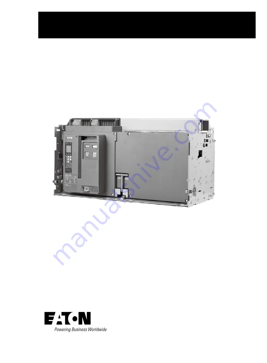
manualshive.com logo in svg
background image

Instruction Manual

 MN013014EN

IZM63 / IN63 low voltage air circuit breaker

IZM63 / IN63

Содержание IZM63

Страница 1: ...Instruction Manual MN013014EN IZM63 IN63 low voltage air circuit breaker IZM63 IN63...

Страница 2: ...are covered in individual instruction leaflets specif ic to the accessory This information is also available from the Eaton Web site at www eaton com For application information consult Eaton or see a...

Страница 3: ...ndary jumpers 5 2 7 Installing drawout circuit breaker 6 2 7 1 Circuit breaker positioning 6 2 7 2 Levering circuit breaker 8 2 8 Fixed circuit breaker 11 2 9 Circuit breaker operation 11 2 10 Technic...

Страница 4: ...VES 32 SECTION 6 WIRING DIAGRAMS 43 SECTION 7 INSPECTION AND MAINTENANCE 51 7 1 General 51 7 2 General cleaning recommendations 51 7 3 When to inspect 51 7 4 What to inspect 51 7 4 1 Functional field...

Страница 5: ...s and arc tracking resistance The drawout IZM63 IN63 circuit breaker is a through the door design having three breaker positions with the compartment door closed CONNECT TEST DISCONNECT and one positi...

Страница 6: ...uipment its operation and the associated haz ards should be permitted to work on the equipment Additionally only qualified personnel should be permitted to install or operate the equipment 2 Always be...

Страница 7: ...ackaging until the breakers are ready for inspection testing and or installation When ready to inspect and install the circuit breaker carefully remove the banding straps and lift off the cardboard bo...

Страница 8: ...e integral molded lifting handles on both sides of the cir cuit breaker Every effort should be made during lifting to minimize circuit breaker swing and tilt If the circuit breaker is to be lifted ont...

Страница 9: ...le rejection interlocks Doing so and using a lower capacity circuit breaker in an incompatible cassette could result in an electrical fault that could result in death bodily injury and or equipment da...

Страница 10: ...ion rails Be certain that the circuit breaker s four molded dra wout rail supports are fully seated in the extension rail cutouts on both sides Figure 2 3 Do not remove the lifting yoke from the circu...

Страница 11: ...ary Connections Not Made Only Ground Connection Made Breaker Still Behind Door Typical Storage Position Circuit Breaker Side View Compartment Front Door Secondary Connection Made Rear of Compartment P...

Страница 12: ...are drive and ratchet which is not provided Figure 2 9 As long as the levering access door is raised the circuit breaker is held trip free Begin by rotating the levering in screw to the full countercl...

Страница 13: ...utomatic primary and sec ondary connections For the IEC circuit breaker a cassette style using horizontal stabs and horizontal customer busbar terminals is available as standard Figure 2 11 The casset...

Страница 14: ...e 2 11 Drawout cassette features front and rear views 2 1 4 3 6 5 8 7 1 1 2 2 3 4 5 6 6 7 7 8 9 9 9 10 10 10 4 Front View Rear View Extension Rails Extension Rail Cutout Secondary Plug in Connectors S...

Страница 15: ...wout circuit break er s type secondary connector Both secondary connection devices are mounted at the top front of the circuit breaker The fixed circuit breaker frame has two mounting feet one on each...

Страница 16: ...erature C 40 45 50 55 60 70 IZM63 5000A 5000 5000 5000 5000 5000 5000 IZM63 6300A 6300 6300 6200 6000 5600 5100 Max operating current A ambient temperature 40 C Circuit breaker frame size IZM63 Recomm...

Страница 17: ...rawout type IZM63N3 V P50 4 10 400 1000 IZM63H3 V P50 4 10 400 1000 IZM63N3 V P63 4 10 620 1550 IZM63H3 V P63 4 10 620 1550 Based on RAC RDC 1 30 the total loss is under the full rated current Deratin...

Страница 18: ...intend ed to provide a guideline for the installation of fixed type or drawout type circuit breakers in an enclosure The diagram and related dimensions can be used for reference Electrical clearance...

Страница 19: ...th configurations and will be discussed in this section The mounting features unique to the drawout and the fixed configurations will be covered individually in Sections 4 and 5 respectively Controls...

Страница 20: ...7 6 2 5 9 10 5 2 1 4 3 6 7 8 9 10 Fixed primary terminal with optional vertical adapter Arc chamber Mounting foot Circuit breaker nameplate Tripper bar Baffled arc chute cover Secondary disconnect Fac...

Страница 21: ...rd frame fixed circuit breaker features front and rear views 5 2 1 4 3 10 7 6 9 8 Arc chamber Mounting foot Circuit breaker nameplate Phase identification labels Tripper bar Baffled arc chute cover Se...

Страница 22: ...indicator Three accessory windows Trip unit Contact status open close Spring status charged discharged Manual OFF button push Manual ON button push Manual charge handle Optional operation counter Pad...

Страница 23: ...n the front of the case and is electrically isolated and insulated from current contact struc tures It is covered by an insulating front cover 3 3 Operating mechanism The IZM63 IN63 operating mechanis...

Страница 24: ...or more details on these devices refer to Section 4 1 and 4 2 in this booklet An electrical operator that is used to charge the closing spring automatically can be added to a manually operated circuit...

Страница 25: ...s PXR 20 PXR 25 LSIG protection Yes Yes Disable I Yes Yes GF protection Option Option GF alarm Option Option Display Yes Yes Programmable No No Current metering Yes Yes Power energy metering No Yes Po...

Страница 26: ...ayed on the LCD screen and In rating printed on the frame rating module battery cover MUST ALWAYS AGREE 3 4 5 Trip actuator The low energy trip actuator is a small electromagnetic device that provides...

Страница 27: ...lied with both plug in connectors male and female just described in the two previous paragraphs The plug in connectors are joined and attached to the top portion of the circuit breaker The customer ca...

Страница 28: ...24 IZM63 IN63 low voltage air circuit breaker MN013014EN May 2021 www eaton com cn Section 4 Dimensional drawings IZM63 IN63 fixed type dimensions and horizontal board dimensions 3P 5000 6300A...

Страница 29: ...25 IZM63 IN63 low voltage air circuit breaker MN013014EN May 2021 www eaton com cn Section 4 Dimensional drawings IZM63 IN63 fixed type dimensions and horizontal board dimensions 4P 5000 6300A...

Страница 30: ...y 2021 www eaton com cn Section 4 Dimensional drawings IZM63 IN63 fixed type panel cutout and external vertical board dimensions 3P and 4P 5000 6300A Max distance to isolation surface Door cut out Doo...

Страница 31: ...air circuit breaker MN013014EN May 2021 www eaton com cn Section 4 Dimensional drawings IZM63 IN63 Withdrawable Type Dimensions 3P and 4P 5000 6300A Notes de Drawer switch position f Recommended mini...

Страница 32: ...1 19 0 6 50 165 10 11 50 292 10 Mounting hole Connected position Test position Withdrawn position Disconnected position Right View Panel cutout size and circuit breaker position Front View Mounting ho...

Страница 33: ...11 10 2 38 1 143 2 210 177 8 177 8 120 7 177 8 177 8 322 5 153 6 4 x 8 9 4 x 19 1 50 3 4 x 13 5 25 4 25 4 279 4 231 9 322 5 6 4 384 1 621 5 Mounting plane Preferred mounting positioning Optional mount...

Страница 34: ...1 3 120 7 241 3 241 3 384 1 475 5 350 351 4 4 x 8 9 6 4 4 x 19 1 50 3 4 x 13 3 25 4 231 9 25 4 279 3 351 3 127 8 22 4 6 places 6 places 4 places 4 places Preferred mounting positioning Preferred mount...

Страница 35: ...age air circuit breaker MN013014EN May 2021 www eaton com cn Section 4 Dimensional drawings IZM63 IN63 withdrawable type cassette horizontal board wiring dimensions 3P 5000 6300A Maximum distance 101...

Страница 36: ...85 C will cause over temperature trip 6 This curve is for 50Hz 60Hz applications 7 These curves are comprehensive for series IZM63 IN63 circuit breakers including all frame sizes ratings and construc...

Страница 37: ...r with 5 tolerance 2 SDPU 1 5x to 10x of Ir have 100 10 tolerance 3 LD Time 0 5s to 24s have 100 0 30 tolerance 4 SD Slope I T The short pickup points have 10 tolerance time setting from 0 1s to 0 5s...

Страница 38: ...termined by the interrupting rating of the circuit breaker 6 Curves applies from 20 C to 70 C ambient Temperatures above 85 C will cause over temperature trip 7 This curve is for 50Hz 60Hz application...

Страница 39: ...igh Instantaneous trip 5 The total Instantaneous clearing times shown are conservative and consider the maximum response times of the trip unit the circuit breaker opening and the interruption of the...

Страница 40: ...ined by the interrupting rating of the circuit breaker 6 Curves applies from 20 C to 70 C ambient Temperatures above 85 C will cause over temperature trip 7 This curve is for 50Hz 60Hz applications 8...

Страница 41: ...ent Rating In 6 The end of the curve is determined by the interrupting rating of the circuit breaker 7 Curves applies from 20 C to 70 C ambient Temperatures above 85 C will cause over temperature trip...

Страница 42: ...Mode Trip 5 The end of the curve is determined by the interrupting rating of the circuit breaker 6 Curves applies from 20 C to 70 C ambient Temperatures above 85 C will cause over temperature trip 7...

Страница 43: ...he other break point and shape of the curve 6 If the short delay time is longer than long delay time the short delay trip time will follow the long time setting 7 If long delay thermal memory is enabl...

Страница 44: ...ue prevailing for bottom of band For all curves the lower flat response time value projected to I T line will determine the other break point and shape of the curve 6 If long delay thermal memory is e...

Страница 45: ...r have 100 10 tolerance 3 LD Time 0 5s to 24s have 100 0 30 tolerance 4 SD Slope I T The short pickup points have 10 tolerance time setting from 0 1s to 0 5s with steps of 0 1s except 0 2s tolerance i...

Страница 46: ...2 On a 4P circuit breaker the neutral current sensor has the same style and wiring method as the phase sensor located within the circuit breaker frame no need to connect the secondary terminals 11N1 1...

Страница 47: ...The Spring Release internal electronics pulse the SR coil and then provides a high impedance circuit This provides anti pumping 4 When the spring discharges its energy the motor switch will re energi...

Страница 48: ...voltage air circuit breaker MN013014EN May 2021 www eaton com cn Section 6 Wiring diagrams Under voltage release IZM series circuit breaker Monitored Voltage 94 93 Notes 1 Treated as the positive volt...

Страница 49: ...r Remote Indication Maintenance Mode indication Contact rating 1 A 120 Vac 1 A 24 Vdc and 0 5 A 230 Vac 2 For the PXR20 25 the Alarm 2 is for High Load alarm Ground Fault alarm Contact rating 1 A 120...

Страница 50: ...a External Neutral Sensor b External Neutral Sensor IZM series circuit breaker PXR 11 N1 N1 12 N2 N2 Notes1 2 Sensor is customer wired to sense neutral currents This is required for 3 pole 4 pole ACB...

Страница 51: ...maximum length of this wiring to remotely arm the switch or alternate relay contact is 63 78 feet 3 m Use 20 AWG wire or larger 4 A remote Stack Light Annunciator panel or other remote indication devi...

Страница 52: ...A LB LC PT MODULE BREAKER A 0 600 L L INPUT B C To additional breakers 16 max Secondary Contacts 1 N 3 5 30 PTVB 29 PTVA 31 PTVC TP2 32 PTVN LN LA LB LC PT MODULE BREAKER A 0 600 L L INPUT B C To addi...

Страница 53: ...3 Notes 1 Twisted together AWG 14 to 20 copper wire Route the Zone Interlock wiring separate from power conductors DO NOT GROUND any Zone Interlock wiring 2 The maximum distance between two farthest...

Страница 54: ...ign objects can be driven into areas such as the breaker mech anism where additional friction sources could create prob lems Never use a wire brush to clean any part of the circuit breaker 7 3 When to...

Страница 55: ...s function Charge the breaker mechanism springs either using the charging handle or the motor operator Close the breaker by applying rated voltage to the spring release accessory and verify closing by...

Страница 56: ...can be viewed by looking directly down into the arc chamber Figure 8 3 and Figure 8 4 A contact wear indicator is provided for each primary contact and indicates whether or not the contact should be r...

Страница 57: ...tact wear indicator with circuit breaker closed Side to Side Ledge Side to Side Ledge Contact Wear Inspection Area ledge not visible under contacts Contact Wear Inspection Area ledge now becoming visi...

Страница 58: ...cuit breaker makes no attempt to close with either local manual or remote controls springs do not discharge Closing spring not fully charged check SPRING CHARGED indicator Charge spring manually check...

Страница 59: ...er THERE ARE NO UNDERSTANDINGS AGREEMENTS WARRANTIES EXPRESSED OR IMPLIED INCLUDING WARRANTIES OF FITNESS FOR A PARTICULAR PURPOSE OR MERCHANTABILITY OTHER THAN THOSE SPECIFICALLY SET OUT IN ANY EXIST...

Отзывы: