background image

INS #

iLumin Plus

Installation Quick Guide

ILS-0010 
ILS-1100 
ILS-0020 
ILS-2000

ILM-2201 
ILM-2200 
ILM-2111 
ILM-2110
ILM-0040

ILM-0041
ILM-3000
ILM-3001
ILM-4000
ILM-4001

ILL-3300
ILL-3301
ILL-4400
ILL-4401

Applies to Model #s:

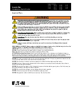
Risk of Fire, Electrical Shock, Cuts or other Casualty Hazards- Installation and maintenance of this 

product must be performed by a qualified electrician. This product must be installed in accordance 

with the applicable installation code by a person familiar with the construction and operation of  

the product and hazards involved. For continued protection against shock hazard replace all covers 

and guards after field wiring is completed.

Before installing or performing any service, the power MUST be turned OFF at the branch circuit breaker. 

According to NEC 240-83(d), if the branch is used as the main switch for a fluorescent lighting circuit,  

the circuit breaker should be marked with “SWD”. All installations should be in compliance with the 

National Electric Code and all state and local codes.

Risk of Fire and Electric Shock- Make certain power is OFF before starting installation or attempting 

any maintenance. Disconnect power at fuse or circuit breaker. iLumin Plus models may contain 

circuits from more than one power source. 

Risk of Burn- Disconnect power and allow fixture to cool before handling or servicing.

Risk of Personal Injury- Due to sharp edges, handle with care. Always use at least two people when 

lifting and mounting heavy or large units

Failure to comply with these instructions may result in serious injury (including death) and property  

damage.

WARNING

DISCLAIMER OF LIABILITY: Eaton assumes no liability for damages or losses of any kind that may arise from the 

improper, careless, or negligent installation, handling or use of this product. 


IMPORTANT:

 Read carefully before installing fixture. Retain for future reference.  

NOTICE:

 Fixture may become damaged and/or unstable if not installed properly. 

Note:

 Specifications and dimensions subject to change without notice.

ATTENTION Receiving Department:

 Note actual fixture description of any shortage or noticeable damage on 

delivery receipt. File claim for common carrier (LTL) directly with carrier. Claims for concealed damage must be 

filed within 15 days of delivery. All damaged material, complete with original packing must be retained.

iLumin Plus 

NOTICE:

 If a room is wired for two circuits using two separate hot leads, it is very important to connect only one 

circuit per relay. Both circuits must be fed from the same phase.

NOTICE:

 Ensure that all modules are firmly seated on the DIN rails before beginning field wiring. 

NOTICE:

 The high voltage supply should be fed to the cabinet via an external isolation breaker with sufficient 

capacity for the planned installation.

NOTICE:

 Ensure that the supply is fully isolated at an external breaker before opening doors. Test that power has 

been removed before starting to handle conductors.

NOTICE:

 Ensure that high voltage and low voltage wiring remains separate. 

NOTICE:

 All new wiring must be fully verified before applying power.

NOTICE:

 Designed for indoor installation and use only. Dry location rated.

Содержание iLumin Plus

Страница 1: ...large units Failure to comply with these instructions may result in serious injury including death and property damage WARNING DISCLAIMER OF LIABILITY Eaton assumes no liability for damages or losses...

Страница 2: ...ow voltage Input Class 2 Low voltage Input Installation steps 1 Mount enclosure 2 Connect panel power 3 Connect relay wiring 4 Connect 0 10V dimmer wiring 5 Connect 2 wire data bus wiring 6 Connect iL...

Страница 3: ...nd discard before field wiring This includes cardboard spacers in small cabinets and plastic tie wraps used on all SCMR relay modules SCMR Branch Circuit OCP SCCR NOTE Cabinets containing SCMR modules...

Страница 4: ...ct operating conditions The cabinets do not contain fans Allowing airflow around the panel will enhance the reliability and longevity of all models Locating panels away from heat generating equipment...

Страница 5: ...l cabinets have been designed to provide a clear layout and logical progression for all power circuits The main supply conductors enter at the top panel Input power is then fed to the modules inside t...

Страница 6: ...on the interior DIN rail per the order specifications Each 0 10V dimmer requires a corresponding relay from the SCMR1220 NA to turn the lighting load ON OFF This mapping is performed during programmi...

Страница 7: ...R1 RJ PC connection device A PC can be connected to the iLumin Plus panel using the SW2 cable kit plugging into the RJ port on the CR1 RJ If this iLumin Plus panel is connected to the lighting network...

Страница 8: ...to access the lighting network via the buildign LAN or VLAN Note The EG2 can be use as a LAN bridge to connect different building lighting networks as a single lighting network over the building LAN...

Страница 9: ...de taille La d sob issance aux instructions suivantes repr sente un risque de blessures y compris la mort et de dommages mat riels AVERTISSEMENT EXON RATION DE RESPONSABILIT Eaton n assume aucune resp...

Страница 10: ...limentation du panneau 3 Raccordement du c blage de relais 4 Raccordement du c blage du gradateur de 0 10 V 5 Raccordement des deux c bles de conducteur du bus de donn es 6 Raccordement du c blage du...

Страница 11: ...que REMARQUE SUR LA PROTECTION CONTRE LES SURINTENSIT S et LE COURANT DE COURT CIRCUIT NOMINAL du circuit r sonance coupl e magn tique Les armoires qui contiennent les modules r sonance coupl e magn t...

Страница 12: ...armoires ne comportent pas de ventilateur Permettre une circulation d air autour du panneau am liorera la fiabilit et la dur e de vie de tous les mod les Installer les panneaux loin du mat riel qui g...

Страница 13: ...et une progression logique pour tous les circuits d alimentation Les conducteurs de l alimentation principale p n trent dans le haut du panneau La puissance d entr e est ensuite aliment e vers les mo...

Страница 14: ...Humidit entre 0 et 95 sans condensation Les modules de gradation SCMH1200 NA sont pr alablement mont s l int rieur du rail DIN conform ment aux sp cifications de la commande Chaque gradateur de 0 10 V...

Страница 15: ...ge Les moyens et les grands panneaux iLumin Plus comprennent le dispositifs de connexion pour ordinateur CR1 RJ Un ordinateur peut tre raccord au panneau iLumin Plus l aide de la trousse de c bles SW2...

Страница 16: ...suite iCANsoft pour le processus de configuration Connexion Ethernet Wiring Information Connection RJ45 connector Use Category 5 or Category 6 cable minimum Connect Connect to building LAN or VLAN for...

Страница 17: ...e estas instrucciones puede provocar lesiones graves incluida la muerte y da os a la propiedad ADVERTENCIA RENUNCIA DE RESPONSABILIDAD Eaton no asume ninguna responsabilidad por da os o p rdidas de ni...

Страница 18: ...te el recinto 2 Conecte la alimentaci n del panel 3 Conecte el cableado del rel 4 Conecte el cableado del atenuador de 0 10V 5 Conecte el cableado del bus de datos de 2 cables 6 Conecte el cableado de...

Страница 19: ...e separadores de cart n en peque os armarios y envolturas de pl stico que se usan en todos los m dulos SCMR rel s Circuito derivado SCMR OCP y SCCR NOTA Los armarios que contienen m dulos SCMR NO incl...

Страница 20: ...miento correctas Los armarios no contienen ventiladores Permitir el flujo de aire alrededor del panel mejorar la confiabilidad y longevidad de todos los modelos La ubicaci n de paneles lejos de equipo...

Страница 21: ...ise ados para proporcionar un dise o claro y una progresi n l gica para todos los circuitos de alimentaci n Los conductores principales de suministro ingresan en el panel superior La corriente de entr...

Страница 22: ...n Los m dulos de atenuaci n SCMH1200 NA se premontar n en el riel DIN interior seg n las especificaciones del pedido Cada atenuador de 0 10V requiere un rel correspondiente del SCMR1220 NA para ENCEND...

Страница 23: ...4 Conect ndose a la red de iluminaci n Los paneles iLumin Plus medianos y grandes incluyen el dispositivo de conexi n CR1 RJ PC Se puede conectar una PC al panel de iLumin Plus utilizando el kit de ca...

Страница 24: ...Category 6 cable minimum Connect Connect to building LAN or VLAN for lighting network access Note The EG2 can be used to access the lighting network via the buildign LAN or VLAN Note The EG2 can be u...

Отзывы: