42
34
2 3
24
4 1
33
13
14
ESR5-BWS-31-24VDC
O
rd
er
N
o.
: 2
9
81
05
9
A
P
P
R
O
V
A
LS
S
e
rial
N
o
.
13
23
33
41
14
2
4 3
4
4
2
41
33
13
1 4
2 4
23
3 4
4 2
ESR5-BWS-31-24VDC
A1
S34
S3
3 S
3 5
A2
S22
S1
2
S11
K 2
K 1
Pow
er
①
②
⑩
⑨
⑧
⑦
⑥
⑤
④
③
1 Description ESR5-BWS-31-24VDC
ESR5-BWS-31-24VDC
11/23 MN049020EN Eaton.com
8
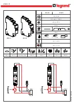
1.8 Operator control and display elements
Figure 1:
ESR5-BWS-31-24VDC
a
Metal lock for installation on the mounting rail
b
Plug-in screw terminals COMBICON
c
13/14, 23/24, 33/34 – non-delayed enable current paths
d
41/42 – signal current path
e
LED status display, green – K2
f
LED status display, green – K1
g
LED status display, green – Power
h
A1, A2 – supply voltage connection
i
S11, S12, S22 – input circuits
j
S33, S34, S35 – starting circuit (activation circuit)
→
The device's year of manufacture can be found underneath the
CE marking on the housing.
XX/XX = calendar week / year