Keysight E1460A, User Manual
The Keysight E1460A is a versatile electronic measurement module that offers precision and reliability. To unlock its full potential, make sure to download the comprehensive User Manual for free from our website. This manual provides detailed instructions and valuable insights to optimize your experience with the E1460A.
Share
Download


Reviews:
No comments
Related manuals for E1460A

MIHO014
Brand: Energenie Pages: 2

4 Relay box
Brand: Neets Pages: 18

Dupline DSM 1U
Brand: Doepke Pages: 8

IACS1A
Brand: GE Pages: 34

ICR51A
Brand: GE Pages: 16

IAV54E
Brand: GE Pages: 32

IBCG51E21
Brand: GE Pages: 16

IFC51A AND 518
Brand: GE Pages: 36

IBCG51M
Brand: GE Pages: 50

P741
Brand: GE Pages: 560

IFC66CD
Brand: GE Pages: 2

EJ Relays
Brand: Panasonic Pages: 4

CR Relays
Brand: Panasonic Pages: 4

IC Drivable PC Board
Brand: Panasonic Pages: 5

ELD V2
Brand: Ampcontrol Pages: 19
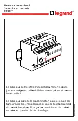
0 038 11
Brand: LEGRAND Pages: 32

2281Q
Brand: Farfisa Pages: 16

CX-12 PLUS
Brand: CAMDEN Pages: 15


