


I.L. 17403
Page 4
Effective 9/04
OVERLOAD CLASS
Use the Class 10 (fast trip) setting for Design E motors,
hermetic refrigerant motor compressors, submersible
pumps, and similar applications, as well as for protecting
general purpose motors where the load permits the motor
to reach rated speed without the overload protection circuit
tripping.
Use the Class 30 (slow trip) setting for special motors driv-
ing high inertia loads such as ball mills, reciprocating
pumps, loaded conveyors, etc.
Use the Class 20 (standard trip) setting for all other applica-
tions. Most NEMA rated general purpose motors will be
protected by a Class 20 setting.
IF A PROPERLY SELECTED TRIP CURRENT SETTING
RESULTS IN AN OVERLOAD TRIP, MOVE TO A HIGHER
CLASS SETTING RATHER THAN TO A HIGHER TRIP
CURRENT SETTING.
Select Class NONE when no overload, phase loss, phase
imbalance, current-sensing, or ground protection is wan-
ted. With NONE selected, the Class W200 motor starter
will behave like a Class W201 contactor.
TRIP CURRENT SETTING
The overload trip current of an Advantage starter is deter-
mined by its program and its DIP switch settings in Positions
5 through 1 as shown in Tables IV and V. Use only the table
appropriate for the starter involved and disregard the other.
For motors with a marked temperature rise of not over
40
o
C or with a service factor of not less than 1.15, find the
range of motor FLA in Column A that includes the FLA of
OVERLOAD
POSITIONPOSITION
CLASS
7
6
10
0
0
20
0
1
30
1
0
NONE
1
1
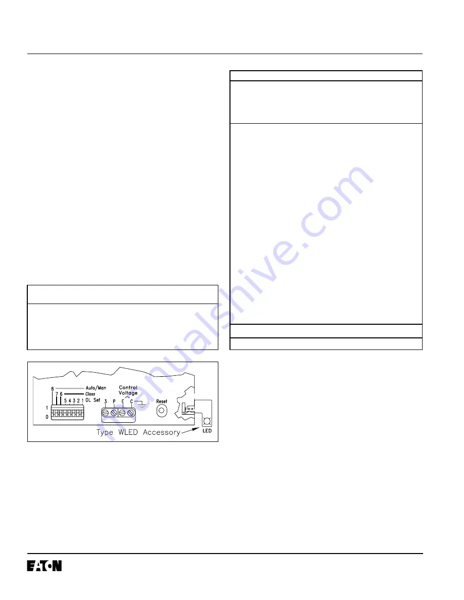
Fig. 3 DIP Switch, Terminals and Reset
TABLE IV - SIZE 3 CURRENT RANGE
*ALL SETTINGS NOT SHOWN ARE EQUIVALENT TO 00000
Replace the arc box cover securely after making selections.
Column A
Column B
Service Factor
Service Factor
DIP Switch
Trip
Setting*
Rating
(Positions
1.15 to 1.25
1.0
(Amps)
54321)
Min.
Max.
Min.
Max.
9.9
-
10.8
10.8
-
11.7
12.4
00000
10.9
-
11.9
11.8
-
12.9
13.6
00001
12.0
-
13.1
13.0
-
14.2
15.0
00010
13.2
-
14.4
14.3
-
15.6
16.5
00011
14.5
-
15.8
15.7
-
17.2
18.1
00100
15.9
-
17.4
17.3
-
18.9
19.9
00101
17.5
-
19.2
19.0
-
20.9
21.9
00110
19.3
-
21.1
21.0
-
22.9
24.1
00111
21.2
-
23.2
23.0
-
25.2
26.5
01000
23.3
-
25.6
25.3
-
27.8
29.1
01001
25.7
-
28.1
27.9
-
30.6
32.1
01010
28.2
-
30.9
30.7
-
33.6
35.3
01011
31.0
-
34.1
33.7
-
37.0
38.8
01100
34.2
-
37.5
37.1
-
40.8
42.7
01101
37.6
-
41.3
40.9
-
44.9
47.0
01110
41.4
-
45.4
45.0
-
49.4
51.7
01111
45.5
-
50.0
49.5
-
54.3
56.9
10000
50.1
-
54.9
54.4
-
59.7
62.6
10001
55.0
-
60.5
59.8
-
65.7
68.8
10010
60.6
-
66.5
65.8
-
72.3
75.7
10011
66.6
-
73.2
72.4
-
79.6
83.3
10100
73.3
-
80.7
79.7
-
87.7
91.6
10101
80.8
-
88.7
87.8
-
90.0
101
10110
88.8
-
90.0
-
111
10111
5300C76
See Tables VI and VII for selection of appropriate short
circuit protective device.
the motor to be protected and use the setting shown for
DIP switch Positions 5 through 1. For all other motors, sel-
ect a range in Column B.
Settings based on Column A give a trip rating of not more
than 125% of motor FLA. Settings based on Column B give
a trip rating of not more than 115% of motor FLA.