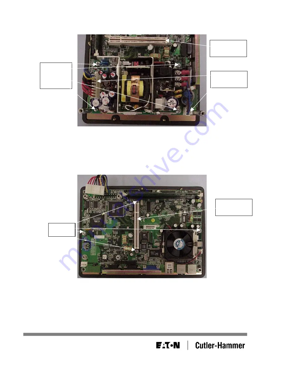
4. Rotate the unit 90°. Remove the screws from the power supply and disconnect the two power
connectors. See Figure 15.
PCI
connector
Power
connectors
Power
supply
screws
Figure 15
Note
: If the unit is an Outdoor Series model, a fan bracket will be mounted above the PCI connector
and wired into the power supply. The fan bracket will need to be unscrewed before the power
supply can be removed from the CPU circuit board
5. Rotate the unit back 90°. Remove the power supply from the board and remove the screws from the
CPU circuit board. See Figure 16.
PCI
connector
Screws
Figure 16
Note
: If the unit is an Outdoor Series model, the screws on either side of the PCI connector will be
replaced with standoffs for a fan bracket which was removed in Step 4. Remove the standoffs
from the CPU cirtcuit board.
January 2006
Page 11 of 14
01-50604-01


