Intelligent Technologies QCPort System Install Manual
November 2005
MN05001002E
For more information visit
www.eatonelectrical.com
Page
8
Multiple Peripherals on One Device Using QCPort
QCPort has been designed to support multiple devices connected to one motor
controller, without the motor controller having prior knowledge of the connected device.
Devices that can be connected to a motor controller include user interface products and
IO products. Once again, the devices are connected to Channel 0 of the motor controller.
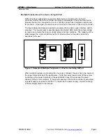
The figure below illustrates an application example that includes a user interface and IO
modules. The input module is used to apply a hard-wired HOA while the output module
is used to annunciate the motor controller status and trip conditions. The mapping of the
data between the motor controller and the IO devices does not require a tool and is
seamless to the user.
Figure 2: Example of Multiple Peripherals on One Device Using QCPort
When multiple devices are connected to one motor controller, the user has to be aware of
the power demand of all of the peripherals. Verify the power requirement of this system
by adding up the power demands of the peripherals to see if they exceed the power
capacity of the motor controller. If the power capacity of the motor controller is exceeded,
a power supply is required for QCPort. To help size the power supply, consult “Locating
a Power Supply” later in the manual.


