10
11
INM MTL9373-FB3 Rev 1
INM MTL9373-FB3 Rev 1
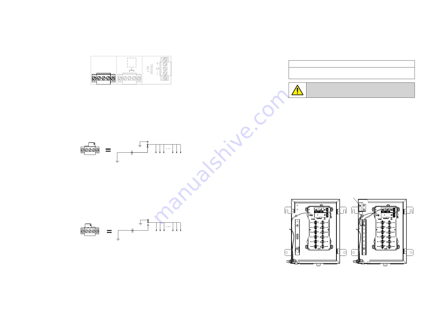
5.2.2 Cable shield grounding
The cable shield is normally electrically isolated from the protective earth
ground, although the two may be deliberately interconnected in some
grounding arrangements, as described below.
The module can be configured by the user to either of two grounding methods
by means of a link in the trunk wiring area of the module – see Figure 5.1 to
locate the grounding terminals.
Figure 5.1
– Cable shield grounding option terminals
The user should adopt the grounding method that conforms to their system’s
normal grounding technique. Whichever method is used, it is important to
connect the screen/shield to a ground at only one end of the cable.
The following two options are available to the user.
Option 1
Figure 5.2
– Effect of Option 1 wiring
In many installations, the preferred and default method of grounding is to
ground the fieldbus cable shields at one point only, normally at the fieldbus
power supply. In this case, the trunk and spur cable shields are connected to
each other at the Fieldbus Barrier module and are not connected to ground
in the field. For this arrangement, fit the link between terminals B and C, as
shown above.
Option 2
Figure 5.3
– Effect of Option 2 wiring
With this arrangement, the fieldbus trunk shield is separated from the spur
cable shields. It should be adopted if plant or local regulations require that the
spur cable shields be grounded at the Fieldbus Barrier. For this arrangement, fit
the link between terminals A and B, as shown above.
T
N/C
A B C
B C
Local
ground
C
B
Host
ground
Trunk
shield
Spur shields
A B
Local
ground
A
B
Host
ground
Trunk
shield
Spur shields
5.3 Trunk cable wiring
The 9373-FB3-PX-SS product has a range of user options for trunk wiring. These
range from a single trunk cable entry; allowance for an onward link to a second
enclosure – as shown in Section 3; and the ability to manage and marshal
multiple, spare trunk pairs if required.
In addition, the option for surge protection on the trunk wiring may have been
specified and details of this are also covered below.
NOTE
The trunk features mentioned above, and discussed below, will have been
specified at the time of ordering and cannot be modified in the field.
WARNING!
No part of the trunk wiring may be worked while the enclosure is
powered, unless the environment is known to be non-hazardous.
5.3.1 Trunk cable access
The enclosure is provided with two access holes for trunk glands in the lower
left floor area of the enclosure – see Figure 4.1 or 4.2; one is for the incoming
trunk and another, if necessary, for onward linking to a second enclosure.
The cable entry holes are factory-fitted with either plastic or metal blanking
plugs, and may be sized as M20, M25 or M32, depending upon the product
type ordered. Fit cable glands that will suit both the diameter of the hole and
the trunk cable.
5.4 Standard Small Enclosure – Trunk Wiring details
There are three simple formats for trunk wiring when the Standard Small
enclosure has been chosen:
a) Single Trunk Input – Without Surge Suppression
b) Trunk Input – Trunk Output – Without Surge Suppression
c) Single Trunk Input – With Surge Suppression
The third option c) is easily identified by the inclusion of the TP-32 surge
suppressor in the upper left area of the enclosure – see Figure 5.4 below.
Figure 5.4 –
Standard Small enclosure – without surge suppressor (left)
– with suppressor (right)
TP-32
Surge
Suppressor


