


8
Place tip of applicator
at top of threaded
portion.
Apply 3 or 4
drops in
each hole.
Figure 14
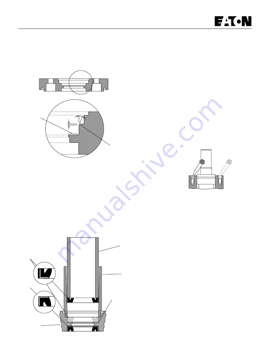
Mounting
Flange
Seal
Driver
Seal
Tube
Back-up Ring
(No Back-up
Ring -008)
Seal Installation Tool
Figure 13
Exclusion
Seal
Shaft
Pressure
Seal
Figure 12
Break Sharp
Corner (see
above note)
Mounting Flange Cross-section
15
°
30
°
,25/,51
[.010/.020]
Inspect for
cracks in this
area of seal
seat
General Purpose Motors
S Series
Reassembly
Important: Prior to installing high pressure shaft seal it is necessary
to break the sharp corner of the flange seal seat, see Fig. 12. Use
400 grit paper to break corner.
22 Clean mounting flange of all loose metallic chips, particles, dirt or
other contamination, including oil. During cleaning, visually check seal
seat in mounting flange for scratches or other marks that might
damage the pressure seal. Check for cracks in flange that might cause
leakage, see Fig. 12.
Important: If a pressure seal installation tool is not available,
temporarily install flange without seals. Then install 2 cap screws
to secure flange to housing. Install seals in flange, and apply
loctite, after you reassemble Gerotor end of motor (see step 41 thru
45 page 11).
Note: If you have a pressure seal installation tool, continue
reassembly, starting with step 23.
23 Lubricate I.D. of seal tube and 0.D. of shaft pressure seal with a
light film of clean petroleum jelly. Align small I.D. end of seal tube with
seal seat in mounting flange. Install back-up ring and pressure seal in
tube—lips of seal face up—see above. Then insert seal driver in tube
to firmly push (by hand with rotating action) seal in seal seat.
Important: After installing seal in flange, examine seal condition. If
cut, damaged, or improperly installed, you must replace it before
continuing reassembly.
24 Install dust seal in flange, see Fig. 15. Press the dust seal into place
carefully. To eliminate damage to rubber portion or distortion of metal
container use a tool (flat-round face 35-41mm[1.37 to 1.62 inch]
diameter) which provides proper guiding and positioning.
25 Install 1.94 inch [50mm] I.D. seal in flange.
Caution: Do not use excessive amount of Loctite.
26 Apply 3 or 4 drops of Loctite adhesive (Loctite no. 601 sealant) at
top of threads in each of 4 holes in housing, see Fig. 14. Do not allow
parts with Loctite applied to surface to contact any metal parts other
than their proper assembly. Wipe off excess Loctite from housing face,
using a non-petroleum base solvent. Do not apply Loctite to threads
more than 15 minutes before installing screws. If housing stands for
more than 15 minutes, repeat application. No additional cleaning or
removal of previous Loctite is necessary.
Содержание Char-Lynn S Series
Страница 2: ...2...


