background image

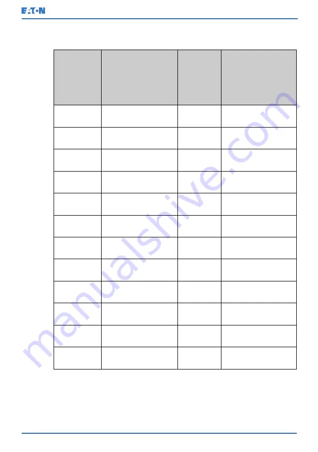
Table 17: Recommended multi-core cable and fuse sizes for rectifier input,
bypass input and UPS output connections

UPS model

Phase cables [mm

2

]

Rectifier,

bypass and

mainte-

nance

bypass

input fuse

[A]

PE cable [mm

2

]

93PM G2 50
(200)

35

100

16

93PM G2 100
(200)

95

200

50

93PM G2 150
(200)

185

315

95

93PM G2 200
(200)

240

400

120

93PM G2 240
(240)

2 x 120

500

120

93PM G2 50
(300)

35

100

16

93PM G2 100
(300)

95

200

50

93PM G2 150
(300)

185

315

95

93PM G2 200
(300)

240

400

120

93PM G2 250
(300)

2 x 120

500

120

93PM G2 300
(300)

2 x 185

630

185

93PM G2 360
(360)

2 x 185

700

240

© Eaton Corporation plc 2020. All rights reserved.

Revision: 001

Document ID: P-164000956

74 (141)

Eaton 93PM G2 UPS 50 – 360 kVA

User’s and Installation Guide

Содержание 93PM G2 Series

Страница 1: ...User s and Installation Guide Eaton 93PM G2 UPS 50 360 kVA P 164000956...

Страница 2: ...restrictions or additional measures may be needed to prevent disturbances The contents of this manual are the copyright of the publisher and may not be reproduced even extracts without the written ap...

Страница 3: ...and battery mode 27 3 3 3 Bypass mode 29 3 4 UPS features 31 3 4 1 Advanced Battery Management 31 3 4 2 Powerware Hot Sync 31 3 4 3 Power Conditioner 32 3 4 4 Frequency Converter 32 3 4 5 Sync Control...

Страница 4: ...ace 65 5 6 3 Relay output interface connections 65 5 6 4 Industrial Relay Card interface connections 66 5 6 5 MiniSlot interface connections 66 5 6 6 Install signal interface connections in a parallel...

Страница 5: ...e UPS system and critical load 101 7 4 10 De energize the critical load 101 7 5 Control a single UPS in a parallel system 102 7 5 1 Start a single UPS 102 7 5 2 Shut down a single UPS 103 7 5 3 Enable...

Страница 6: ...ental specifications 116 10 Warranty 118 10 1 General information about warranty 118 10 2 Whom to contact in case of Warranty 119 APPENDIX A Relay alarms 120 APPENDIX B Recommended secure hardening gu...

Страница 7: ...achine CAUTION CAUTION indicates a hazard with a low level of risk which if not avoided could result in minor or moderate injury or damage to the machine NOTE Notes are used to indicate important info...

Страница 8: ...symbols are used in warnings and notifications to indicate an action that should not be taken The prohibited action symbols are shown below No smoking Limited or restricted access Eaton Corporation pl...

Страница 9: ...an action that must be taken The mandatory action symbols are shown below Wear eye protection General symbol for mandatory action Read the manual or instructions Disconnect from power source Eaton Cor...

Страница 10: ...e defined Screen type represents information that appears on the screen or LCD 1 4 Glossary The following acronyms are used in Eaton documentation to refer to Eaton UPS products or their parts Table 1...

Страница 11: ...put Breaker REPO Remote Emergency Power Off RIB Rectifier Input Breaker RIS Rectifier Input Switch SCR Silicon Controlled Rectifier SSM Static Switch Module STSW Static Switch UPM Uninterruptible Powe...

Страница 12: ...alified service personnel authorized by Eaton There are no user serviceable parts inside the UPS The UPS operates with mains battery or bypass power It contains components that carry high currents and...

Страница 13: ...utput terminals could be energized even when the UPS is turned off WARNING Batteries present a risk of electrical shock or burn from high short circuit current Obey proper precautions Electric energy...

Страница 14: ...tion before you work on the batteries the risk of an electric shock is less likely Discard batteries according to your local disposal requirements Do not dispose of batteries in a fire When exposed to...

Страница 15: ...ser precautions The only permitted user operations Startup and shutdown of the UPS excluding the commissioning startup Use of the LCD control panel Use of optional connectivity modules and their softw...

Страница 16: ...n 2 6 Symbols on the UPS and accessories The following are examples of symbols used on the UPS or its accessories The symbols are used to alert you of important information RISK OF ELECTRIC SHOCK Indi...

Страница 17: ...ing scheduling initial startup regional locations and telephone numbers a question about any of the information in this manual a question that this manual does not answer NOTE For more information abo...

Страница 18: ...e effect on production equipment due to unexpected power problems The Eaton UPS continually monitors incoming electrical power and removes the surges spikes sags and other irregularities that are inhe...

Страница 19: ...M G2 UPS cabinet determines the attainable output power of the UPS The static bypass line consists of static switch a back feed protection isolation device and fuses designed to protect the static swi...

Страница 20: ...in parts outside 1 Control panel 2 Door 3 Bolts 4 Right panel Eaton Corporation plc 2020 All rights reserved Revision 001 Document ID P 164000956 20 141 Eaton 93PM G2 UPS 50 360 kVA User s and Install...

Страница 21: ...5 6 UPM 6 7 Communication interface 8 Internal battery breaker option 9 Connector area 10 Static switch module SSM Eaton Corporation plc 2020 All rights reserved Revision 001 Document ID P 164000956 2...

Страница 22: ...switch BIS 9 Maintenance bypass switch MBS S2 10 Handle for the maintenance bypass switch MBS 11 DC interface compartment 12 Communication interface 13 Connector area 3 3 UPS operating modes The UPS o...

Страница 23: ...itical load is supported securely by utility power through the static bypass switch with double conversion available on demand with typically less than a 2 ms transition time should any abnormal condi...

Страница 24: ...E Battery Closed Open Three phase AC input power is converted to DC using a multilevel converter with IGBT devices to produce a regulated DC voltage to the inverter The UPS status indicated on the di...

Страница 25: ...ning UPSs support the load in the double conversion mode 3 3 1 2 Variable Module Management System mode When Variable Module Management System VMMS mode is enabled the load is powered by UPMs in doubl...

Страница 26: ...mode Figure 6 Path of current through the UPS in the Energy Saver System mode A Static switch 1 Bypass input Main power flow B Rectifier 2 Rectifier input Energized C Inverter 3 Output De energized D...

Страница 27: ...ch is practically seamless When the power conditions are within acceptable limits the UPS operates as a high efficiency energy saving system The energy saver system increases system efficiency up to 9...

Страница 28: ...y K1 opens and the UPS output is powered from the batteries through the inverter As the inverter operates uninterrupted through the transition the load remains supported continuously without disturban...

Страница 29: ...he DC source to restore the capacity 3 3 3 Bypass mode CAUTION The critical load is not protected while the UPS is in bypass mode The UPS automatically switches to the bypass mode if it detects an ove...

Страница 30: ...available to the output of the system in the bypass mode The static bypass consists of a solid state silicon controlled rectifier SCR static switch STSW and a backfeed protection isolation device K5...

Страница 31: ...ry charging is resumed when necessary 3 4 2 Powerware Hot Sync The Eaton Powerware Hot Sync technology is an algorithm that eliminates the single point of failure in a parallel system and therefore en...

Страница 32: ...uency for example 60 Hz output 50 Hz input The UPS can also support high nonlinear loads without iTHD on the input The UPS meets the qualifications outlined in this product specification except for th...

Страница 33: ...lly as an option for 200 kW 240 kVA frames or in an external enclosure as an accessory item 3 6 2 Top air exhaust kit The top air exhaust kit is used to direct the UPS cooling air front to top The kit...

Страница 34: ...type of batteries or other energy storage means consult a certified service technician before you proceed with the installation The UPS can be equipped with an external battery system Eaton offers ex...

Страница 35: ...m static bypass should be chosen according to the future maximum load rating and the number of UPMs is chosen according to the capacity requirements on day one The following UPS configurations with di...

Страница 36: ...Touch screen display X X Battery start X X Integrated backfeed protection X X Static bypass protective fuses X X Internal maintenance bypass switch MBS O Battery breaker for external batteries O O Sy...

Страница 37: ...ntract for the UPS Contact service in advance usually a two week notice is required to reserve a preferred startup date 4 2 Create an installation plan Before you install the UPS system read and under...

Страница 38: ...the EPO between pins 1 and 2 OPTIONAL Alarm relays and signal outputs are wired appropriately OPTIONAL A remote battery disconnect control is mounted in its installed location and its wiring is termin...

Страница 39: ...that can if ignored create issues The creation of micro climates which are persistent variations of temperature and or RH within a single room for example one side of the room is always cooler than th...

Страница 40: ...ating environment must meet the weight requirements shown in Table 4 UPS cabinet maximum weights and the size requirements shown in Table 5 UPS cabinet dimensions Table 4 UPS cabinet maximum weights U...

Страница 41: ...x D x H mm 93PM G2 Shipping dimensions 1000 x 1200 x 2168 Cabinet dimensions 800 x 990 x 1987 Figure 10 93PM G2 UPS top dimensions with top air exhaust option Figure 11 93PM G2 UPS top dimensions wit...

Страница 42: ...re shown in Table 6 UPS cabinet clearances Table 6 UPS cabinet clearances Eaton 93PM G2 xxx 200 and 93PM G2 xxx 300 models Eaton 93PM G2 xxx 240 and 93PM G2 xxx 360 models From the top of the cabinet...

Страница 43: ...to achieve a long life of the UPS and batteries The cooling air entering the UPS must not exceed 40 C Avoid high ambient temperature moisture and humidity For ventilation requirements see 93PM G2 heat...

Страница 44: ...input and UPS output connections and 10 Minimum recommended multi core cable and fuse sizes for battery connection Cable sizes are based on using the specified breakers If cables are run in an ambient...

Страница 45: ...5 200 50 93PM G2 150 200 185 315 95 93PM G2 200 200 240 400 120 93PM G2 240 240 2 x 120 500 120 93PM G2 50 300 35 100 16 93PM G2 100 300 95 200 50 93PM G2 150 300 185 315 95 93PM G2 200 300 240 400 12...

Страница 46: ...short circuit current battery port kA 93PM G2 xxx yyy 4 4 Table 10 Minimum recommended multi core cable and fuse sizes for battery connection UPS model Battery cable pos neg line mm2 Battery fuse A 93...

Страница 47: ...d UPS output bypass UPS model Rated voltage V Rectifier input UPS output bypass Rated current A Rated current A Maximum current A 93PM G2 50 200 380 90 95 76 400 86 95 72 415 83 95 70 93PM G2 100 200...

Страница 48: ...0 285 228 400 258 285 217 415 248 285 209 93PM G2 200 300 380 360 380 304 400 343 380 289 415 331 380 278 93PM G2 250 300 380 450 475 380 400 429 475 361 415 413 475 348 93PM G2 300 300 380 540 570 53...

Страница 49: ...693 93PM G2 300 300 682 832 93PM G2 360 360 0 9 PF 736 898 Maximum battery current calculated at rated load in the end of discharge of VRLA battery 1 67 V per cell Table 14 UPS power cable termination...

Страница 50: ...UPS output bypass and 13 Rated and maximum currents for rated power and voltage battery in accordance with the national and local installation rules The line to line unbalanced output capability of t...

Страница 51: ...nstructions are not closely followed the cabinet may tip over and cause serious injury Do not tilt the UPS cabinet more than 10 degrees from the vertical or the cabinet may tip over For transportation...

Страница 52: ...here are no signs of shipping damages Examine the indicators See the DropNTell inside the package Eaton Corporation plc 2020 All rights reserved Revision 001 Document ID P 164000956 52 141 Eaton 93PM...

Страница 53: ...used for moving the cabinet off of the pallet is delivered on top of the cabinet Eaton Corporation plc 2020 All rights reserved Revision 001 Document ID P 164000956 53 141 Eaton 93PM G2 UPS 50 360 kVA...

Страница 54: ...llet 5 Turn the leveling feet counterclockwise to lift them off of the pallet Eaton Corporation plc 2020 All rights reserved Revision 001 Document ID P 164000956 54 141 Eaton 93PM G2 UPS 50 360 kVA Us...

Страница 55: ...to the pallet NOTE After you have removed the shipping brackets move the cabinet immediately away from the pallet 8 Move the cabinet off of the pallet using the ramp Eaton Corporation plc 2020 All ri...

Страница 56: ...position attach the shipping brackets on both sides of the cabinet with the angle facing outward It is recommended to attach the lower cover plates to the ends of the cabinet included in the package E...

Страница 57: ...h the bottom or top of the cabinet Control wiring can be routed through the rear bottom or top of the cabinet with connections made to easily accessible terminals See Figures 13 Removing the right pan...

Страница 58: ...l and tighten the screws 9 If installing a parallel system repeat the above steps to all units in the system Figure 13 Removing the right panel Figure 14 Gland plate locations 1 Top exhaust fan panel...

Страница 59: ...ss gland plate 4 Top cable access gland plate 5 Rear communication cable conduit Figure 15 Cable support beams Eaton Corporation plc 2020 All rights reserved Revision 001 Document ID P 164000956 59 14...

Страница 60: ...put L1 5 Rectifier input L2 6 Rectifier input L3 7 Bypass input L1 8 Bypass input L2 9 Bypass input L3 10 Neutral 11 UPS output L1 12 UPS output L2 13 UPS output L3 Eaton Corporation plc 2020 All righ...

Страница 61: ...ernal batteries The batteries are designed to deliver a large amount of energy and an incorrect connection may lead to a short circuit and cause serious injuries to the personnel or damages to the equ...

Страница 62: ...e any other type of batteries contact your Eaton representative 5 3 1 Battery trip wiring The external battery breakers can be tripped switched off by energizing its shunt trip coil The shunt trip coi...

Страница 63: ...Cable entry to the UPS is always on the top or the bottom of the cabinet NOTE If batteries are wired outside the cabinets follow the installation instructions given in Section 4 4 3 UPS system power w...

Страница 64: ...signal input connectors for customers which can be used for giving remote control commands to the UPS Customer interface connector TB1 can be used for these purposes Each input is a dry relay contact...

Страница 65: ...ing interface When the original accessory battery cabinet from the manufacturer is used the battery breaker interface wiring is provided with the cabinet The wiring is connected to the X8 terminal in...

Страница 66: ...NC or NO to select the Normally Open or Normally Closed option 4 Install the INDRELAY MS into an open MiniSlot communication bay in the UPS cabinet Figure 20 Industrial Relay Card INDRELAY MS 5 6 5 M...

Страница 67: ...as long as there is always one or more UPS online than required to support the load The system is paralleled for capacity if all UPSs in a system are required to support the load Communication betwee...

Страница 68: ...nce and service Design considerations assume that each UPS has a Module Output Breaker MOB The breaker should also disconnect the neutral for improved safety during maintenance The MOB must have a For...

Страница 69: ...tem wiring length must be equal to ensure approximately equal current sharing when in the bypass mode For proper operation the following must be true 1A 1B 2A 2B 3A 3B 4A 4B Any differences in wire le...

Страница 70: ...n each MiniSlot when using a suitable connectivity device These inputs can be configured with action items The following action items affect all the UPSs in the system When an action item is active on...

Страница 71: ...S system A UPS 1 1 CAN B UPS 2 2 Pull chain C UPS 3 if installed D UPS 4 if installed NOTE This drawing is for distributed bypass wiring purposes and it is not a floor layout plan UPSs can be placed i...

Страница 72: ...lel connector UPS 1 5 GND ISP B External parallel connector UPS 2 6 Earth C External parallel connector UPS 3 7 CANBL 1 External pull chain 8 CANB_1 2 GND S Terminate the first and last UPS with a jum...

Страница 73: ...ust be provided by designated personnel For external wiring use copper cable rated for 70 C at minimum See the appropriate information in Tables 17 Recommended multi core cable and fuse sizes for rect...

Страница 74: ...95 200 50 93PM G2 150 200 185 315 95 93PM G2 200 200 240 400 120 93PM G2 240 240 2 x 120 500 120 93PM G2 50 300 35 100 16 93PM G2 100 300 95 200 50 93PM G2 150 300 185 315 95 93PM G2 200 300 240 400 1...

Страница 75: ...short circuit current battery port kA 93PM G2 xxx yyy 4 4 Table 19 Minimum recommended multi core cable and fuse sizes for battery connection UPS model Battery cable pos neg line mm2 Battery fuse A 9...

Страница 76: ...d UPS output bypass UPS model Rated voltage V Rectifier input UPS output bypass Rated current A Rated current A Maximum current A 93PM G2 50 200 380 90 95 76 400 86 95 72 415 83 95 70 93PM G2 100 200...

Страница 77: ...0 285 228 400 258 285 217 415 248 285 209 93PM G2 200 300 380 360 380 304 400 343 380 289 415 331 380 278 93PM G2 250 300 380 450 475 380 400 429 475 361 415 413 475 348 93PM G2 300 300 380 540 570 53...

Страница 78: ...693 93PM G2 300 300 682 832 93PM G2 360 360 0 9 PF 736 898 Maximum battery current calculated at rated load in the end of discharge of VRLA battery 1 67 V per cell Table 23 UPS power cable termination...

Страница 79: ...UPS output bypass and 22 Rated and maximum currents for rated power and voltage battery in accordance with the national and local installation rules The line to line unbalanced output capability of t...

Страница 80: ...nection to accessories 2 USB device connection to computer 3 Signal inputs 4 External parallel interface 5 RS 232 port for service 6 Emergency Power Off EPO 7 Relay output 8 MiniSlot 1 9 MiniSlot 2 10...

Страница 81: ...t Figure 28 Network M2 card Industrial Gateway Card INDGW M2 This card has all the features and capabilities of the Gigabit Network Card In addition it also provides direct integration of system level...

Страница 82: ...rd provides a way of connecting the UPS to industrial and electrical monitoring systems It also enables a wide range of control applications by allowing up to 250 volts and 5 Amperes through its 5 rel...

Страница 83: ...aster recovery and load shedding features in virtualized environments Intelligent Power Protector IPP is a shutdown agent with basic monitoring and alarming capability It provides automatic graceful s...

Страница 84: ...iguring relays The 93PM G2 offers one native relay output Additionally each of the four MiniSlots can be equipped with a 5 relay adapter for additional relay outputs These instructions guide you throu...

Страница 85: ...ld 3 Enter the password 0101 and press 4 Select Continue 5 Select Configuration and then Relays Outputs Figure 34 Selecting Relay Outputs in the Configurations screen Eaton Corporation plc 2020 All ri...

Страница 86: ...is activated MiniSlot 1 MiniSlot 2 MIniSlot3 MiniSlot 4 Figure 35 Options for relay outputs configuration 7 Enter the code s of the function s that you want to trigger the relay when they become activ...

Страница 87: ...LED is lit Relay 3 352 Alarm LED is lit Relay 4 261 On Bypass LED is lit Relay 5 15 Low Battery warning Alternatively you can configure the relays with any event you want 10 You can test the relays by...

Страница 88: ...put connector with voltage supply 3 K1 thru K5 terminal connec tions for relay contacts to op erator s monitoring equipment Eaton Corporation plc 2020 All rights reserved Revision 001 Document ID P 16...

Страница 89: ...wing nominal voltages 380 400 or 415 VAC Before you start to operate the UPS confirm the UPS nominal voltage and frequency from the display by selecting Settings Information If the UPS need to be oper...

Страница 90: ...splay are status indicators They are colored light emitting diode LED lamps and they work in conjunction with the alarm horn to let you know the operating status of the UPS Table 25 Status indicators...

Страница 91: ...d right sides of the UPS cabinet door The LEDs are red green and yellow RGY The color of the LED is used to indicate the condition of the UPS The most urgent condition is always the one shown Only one...

Страница 92: ...Only one color is shown at a time The table below defines the color coding Table 27 Color LED indicators Color LED indicators UPM UPM status UPM starts up UPM in online battery or EnergyAware mode UP...

Страница 93: ...dicate alarms or events When an alarm occurs first examine these indicators to see what type of event has taken place System event messages When a system event occurs a message appears in the status b...

Страница 94: ...tatus EAA controls ESS Enable Disable Configure VMMS Enable Disable Configure Enable High Alert Clear status ABM Enable Disable Configure Clear Alarms Clear Logs Mimics UPS mimics An overview of the U...

Страница 95: ...by pressing on different statistics Settings User Configuration Service Configurable user settings For details see Section 7 2 4 1 User settings 7 2 4 1 User settings The UPS includes information for...

Страница 96: ...test HMI backlight Adjust the backlight brightness Control P W level 1 Change the level 1 password or remove the password on level 1 The default value is 1111 Control P W level 2 Change the level 2 p...

Страница 97: ...er 2 Close the UPS bypass input feeder circuit breaker 3 Wait for the UPS control panel display to become active and to indicate logic power 4 Repeat steps 1 3 for each individual UPS in the system 5...

Страница 98: ...ot available and the critical load needs to be energized do this 1 Close the UPS input feeder circuit breaker 2 Close the UPS bypass input feeder circuit breaker 3 Wait for the UPS control panel to be...

Страница 99: ...rocessor remains on and an alarm sounds The UPS system now operates in the bypass mode and the yellow bypass status indicator is lit The UPM status is shown as Ready The system status is shown as ON B...

Страница 100: ...thorized Customer Service Engineer To transfer the critical load to the double conversion mode 1 In the home screen press Controls 2 Select EAA controls 3 Select Enable VMMS The entire UPS system tran...

Страница 101: ...ts are shut down as well 7 4 10 De energize the critical load Initiate a UPS system Load Off by pressing the Load Off button in the Controls System Controls screen This button can be pressed to contro...

Страница 102: ...e conversion mode The yellow status indicator on the UPS control panel indicates that the UPS is in the bypass mode If auto bypass is not enabled the UPS output remains off until the UPS system transf...

Страница 103: ...ontrol instructions 7 6 1 Start the UPMs Make sure that the load level does not exceed the single UPM capacity To start an individual power module in the double conversion mode 1 Close the UPS input f...

Страница 104: ...ut down if doing so would lead to an overload condition in the remaining UPMs or UPSs in the system To shut down a single UPM 1 In the home screen press Controls The System controls screen is displaye...

Страница 105: ...witch 1 Press the EPO push button switch The input output and bypass backfeed relays open the battery breaker or disconnect is tripped and the power module is turned off immediately without asking for...

Страница 106: ...on the maintenance bypass switch MBS This connects the feed from the bypass input to the UPS output 5 Turn off the bypass input switch BIS This disconnects the feed for the static bypass module 6 Do t...

Страница 107: ...ypass switch MBS C UPS output X3 7 9 Turn the UPS from the maintenance bypass mode to the double conversion mode To turn the UPS back to the double conversion mode Eaton Corporation plc 2020 All right...

Страница 108: ...t 5 Start the UPS system in the bypass mode a Make sure the UPS input and bypass if dual feed feeder circuit breakers are ON position b In the home screen select Controls System controls Go to bypass...

Страница 109: ...online button Confirm your selection The UPS is now in the double conversion mode Figure 42 Normal positions of the switches A Bypass input 1 Bypass input switch BIS B Rectifier input 2 Maintenance by...

Страница 110: ...necting the utility power and the DC power authorized service personnel must wait at least 5 minutes for capacitor bleed off before attempting internal access to the UPS module DANGER LETHAL VOLTAGE D...

Страница 111: ...nect a terminal first disconnect the charging source Determine if the battery is inadvertently grounded If it is remove the source of the ground Contact with any part of a grounded battery can result...

Страница 112: ...lamp is lit or the normal mode status indicator is not lit contact an Eaton service representative 8 3 2 Monthly maintenance Do this once a month 1 Examine the system parameters on the control panel s...

Страница 113: ...attery bank before you discard the UPS or its battery cabinet Obey the local requirements regarding battery recycling or disposal WARNING Only authorized personnel are allowed to remove the batteries...

Страница 114: ...or kill people and damage equipment Do not discard unwanted batteries or battery material in the public waste disposal system Obey all the applicable local regulations regarding the storage handling a...

Страница 115: ...c compatibility EMC IEC 61000 2 2 Low frequency conducted IEC 61000 4 2 ESD IEC 61000 4 3 RF electromagnetic field IEC 61000 4 4 Fast transient burst IEC 61000 4 5 Surge IEC 61000 4 6 Conducted RF com...

Страница 116: ...20 C 25 C Temperature range operation Eaton 93PM G2 xxx 240 and 93PM G2 xxx 360 models 5 C 35 C Recommended range 20 C 25 C Temperature range storage and transportation 25 C 55 C Relative Humidity Re...

Страница 117: ...se condensation on colder surfaces For more technical details please refer to the technical specification of the 93PM G2 Eaton Corporation plc 2020 All rights reserved Revision 001 Document ID P 16400...

Страница 118: ...other qualified service personnel authorized by Eaton Otherwise the warranty will be voided If the product fails to meet its published specifications due to a defect in material and workmanship cover...

Страница 119: ...re the unit was purchased Have the following information available Purchase order number and purchase order date Installation date OR Serial number and part number of the unit information available on...

Страница 120: ...ad Capacity Off 116 Adaptive Overload Capacity Off 326 Alternate Sync Sync Box 317 Alternate Sync Error 318 Ambient Over Temperature 94 Ambient Temperature Changed 331 Auto calibration in progress 321...

Страница 121: ...Replacement Due 472 Battery Replacement Reminder Set 475 Battery Startup Failure 108 Battery Switchgear Failed 70 Battery Switchgear Open Closed 64 Battery Test Aborted 460 Battery Test Failed 46 Batt...

Страница 122: ...n 315 Bypass Sync Out of Range 268 Bypass Under Over Frequency 194 Capacitor Fan Replacement Due 473 Capacitor Fan Replacement Reminder Set 476 Charger Failed 84 UPM received Charger Off Command 41 Ch...

Страница 123: ...wer 425 CSB EEPROM Version Downgrade 464 CSB Software Incompatible 426 DC Link Over Voltage 10 DC Link Under Voltage 11 Disable ABM Command 447 Disable ESS Command 444 Disable HRS Command 456 Disable...

Страница 124: ...vailable 307 Exit ECT Mode Abnormally 80 Exit ESS Mode 205 External CAN Abnormal or Configuration Mismatch 265 External Communications failure 463 Fan Failed 48 Fan Power Board Cool Fan Failed 305 Fre...

Страница 125: ...Over Voltage 1 Inverter AC Under Voltage 0 Inverter Fault 7 Inverter Matched to Output 105 Inverter On Off 23 Inverter Output Over Current 9 Inverter Over Temperature 6 Inverter Over Temperature Trip...

Страница 126: ...m Failed 240 MCU Software Incompatible 210 MIS Installed 291 MIS Open Closed 292 MOB Open 279 Not Enough Bypass Capacity 272 Not Enough Redundant UPMs 323 Not Enough UPMs 271 On Alarm LED Is Lit 416 O...

Страница 127: ...ot 236 Output Not In Sync With Bypass 286 Output Not In Sync with Ext Sync 287 Output Overload Trip 302 Output Phase Rotation 199 Output Sync Out of Range 267 Output Under Over Frequency 197 Output Vo...

Страница 128: ...ded 428 Preventive Maintenance Reminder Set 474 Pull Chain 81 Pull Chain 234 Pull Out Not Allowed 112 Rectifier Breaker Open 18 Rectifier Fault 104 Rectifier Input Over Current 8 Rectifier On Off 55 R...

Страница 129: ...nal Input 4 On 410 Signal Input 5 On 411 Signal Input 6 On 412 Signal Input 7 On 413 Signal Input 8 On 451 Signal Input 9 On 452 Signal Input Battery Disconnected 402 Signal Input Bypass Sync Disabled...

Страница 130: ...er Off 398 Signal Input Remote Sync 399 Signal Input Remote UPS On 388 Signal Input Remote VMMS Command 394 Signal Input Remote VMMS ESS Off 393 Signal Input Reset Alarms 396 Signal Input Transformer...

Страница 131: ...Test in Progress 259 To Bypass Command 221 Too Many EEP Written Operation 468 Too Many Inverter Transfers 65 Too Many Inverter Transfers 285 Too Many Battery Transfers 106 Transformer Fan Failed 324...

Страница 132: ...and 323 UPM On ECT 87 UPM On Normal 59 UPM On Command 39 UPM Remote Emergency Power Off 45 UPM Selective Trip 51 UPM Shutdown Imminent 14 UPM Software Incompatible 44 UPM State Request 57 UPM Test Com...

Страница 133: ...UPS PhaseB Overload Level4 252 UPS PhaseC Output Overload 244 UPS PhaseC Overload Level2 247 UPS PhaseC Overload Level3 250 UPS PhaseC Overload Level4 253 UPS Ready 238 UPS Shutdown 212 UPS Starting 2...

Страница 134: ...Name ID VMMS Enable 228 VMMS Installed 227 Eaton Corporation plc 2020 All rights reserved Revision 001 Document ID P 164000956 134 141 Eaton 93PM G2 UPS 50 360 kVA User s and Installation Guide...

Страница 135: ...ng information manufacturer type serial number f w version number and location Users can extract device information at locations mentioned below Product number serial number and UPS name are listed on...

Страница 136: ...ch user having their own unique password Security controls will be weakened as soon as the users start sharing the password Restrict administrative privileges Threat actors are increasingly focused on...

Страница 137: ...ny security vulnerability getting discovered in its products our company patches the vulnerability and releases an information bulletin through its cybersecurity web site http eaton com cybersecurity...

Страница 138: ...ity May 2015 https ics cert us cert gov Standards and References 4 National Institute of Technology NIST Interagency Guidelines on Firewalls and Firewall Policy NIST Special Publication 800 41 October...

Страница 139: ...modes 22 M Menu structure of the 93PM G2 UPS User settings 95 N Normal operating modes Variable Module Management System mode 25 O Options and accessories Field installed UPM 33 Internal battery brea...

Страница 140: ...Unpack and unload the UPS 51 UPS maintenance Annual maintenance 113 Battery maintenance 113 Important safety instructions 110 Maintenance training 114 Monthly maintenance 112 Preventive maintenance 1...

Страница 141: ...Copyright 2020 Eaton Corporation plc All rights reserved Unauthorized copying and lending are prohibited Eaton Power Quality Oy Koskelontie 13 FI 02920 Espoo Finland www eaton eu...

Отзывы: