
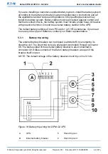


Figure 19: Connections of the EPO switch
NOTE: In "Normally closed" (B) situation a jumper between pins 3 and 4 is
needed.
Table 16: Remote EPO wire terminations
From remote EPO switch
To user interface terminal
block EPO in UPS
cabinet
Remarks
NO
3-4
NC
1-2
Wire jumper between 3-4
must be installed for proper
functions
5.6
Install interface connections
The 93PM G2 UPS contains a total of five (5) signal input connectors for
customers which can be used for giving remote control commands to the UPS.
Customer interface connector TB1 can be used for these purposes. Each input is
a dry relay contact input and requires two wire signaling. None of the inputs are
pre-programmed but need to be separately programmed by qualified service
personnel.
NOTE: When using an external battery system, Eaton recommends you to
connect external signal wiring.
© Eaton Corporation plc 2020. All rights reserved.
Revision: 001
Document ID: P-164000956
64 (141)
Eaton 93PM G2 UPS 50 – 360 kVA
User’s and Installation Guide


