


Seismic Data Requirements for Eaton UPS Equipment Installation User’s Guide 164000050—Rev 05
3
Consideration must be given to attachments (conduits, bus duct, etc.) made to the top of the equipment.
Attachments must have provisions to accommodate the displacement of the equipment indicated in
Entry from the bottom of the equipment eliminates the need for accommodating this motion for attachments.
22..22
C
Ceenntteerr ooff G
Grraavviittyy
For seismic calculations, the center of gravity can be approximated using the dimensions in
with
respect to the left side bracket's front mounting hole (x,y,z origin). UPS center of gravity dimensions are with
batteries installed.
Table 3. 9x55 Unit Center of Gravity Specifications
Type
X (left to right)
Y (front to rear)
Z (bottom to top)
8-15 kVA UPS, 2 High
81 mm
452 mm
406 mm
8-15 kVA UPS, 3 High
81 mm
452 mm
610 mm
8-15 kVA EBC, 2 and 3 High
81 mm
452 mm
406 mm, 2 High
610 mm, 3 High
20-30 kVA UPS Cabinet
178 mm
475 mm
838 mm
20-30 kVA Options Cabinet
178 mm
275 mm
838 mm
22..33
P
Poow
weerr C
Caabblleess
It is recommended that power cables be lashed together at least every meter within the equipment. Refer to
the appropriate Eaton UPS instruction and operation manual for other requirements related to securing power
cables.
22..44
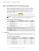
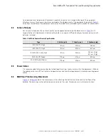
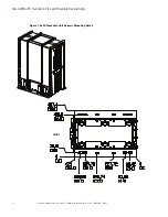
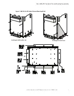
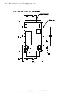
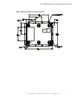
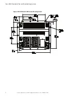
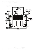
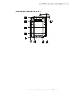
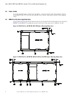
99xx5555 FFlloooorr P
Pllaann S
Seeccuurriinngg D
Diim
meennssiioonnss
and
detail the measurements for attaching the 9x55 seismic brackets to the floor of the
building. The drawings are for reference only and are not to scale. Dimension are in millimeters (inches).
Содержание 9 55 Series
Страница 62: ...16400005005 164000050 05...


