manualshive.com logo in svg
background image

5

Instruction Booklet 

IB0191002EN

Effective November 2019

EAFR-101C arc point sensor relay  

user manual 


EATON

 www.eaton.com

3.3 Push-button description

The EAFR-101C contains one single push-button (SET) that can be 

used for all operational functions of the relay .  The push-button is 

used to initialize the auto-configuration of the system (see Section 

3 .3 .1) and for resetting the indicators and latched output relays .

3.3.1 Auto configuration (System setup)

When all sensors and binary lines have been connected, an 

auto-configuration procedure must be executed .  The initializa-

tion sequence is performed by pressing the “Set” button for two 

seconds .  The EAFR-101C sensor LEDs and all binary LEDs start 

blinking .  The relay scans these inputs to see if they are connected 

and when an input is detected, the corresponding LEDs are illu-

minated to mark that a connection was found .  The inputs without 

connection continue blinking during the remaining three seconds .  

After five seconds, all LEDs are turned off .  During this system 

setup, the dipswitch setting are also stored in non-volatile memory .
All sensor inputs will remain operational even when they are not 

auto-configured .  The auto-configuration is only used for self-supervi-

sion purposes .

ote: 

N

To redo auto-configuration for a relay containing fewer connections 

(binary inputs/outputs or sensors) than in a previously memorized set-up, 

a dipswitch (any one) must be moved back and forth prior to perform-

ing auto-configuration .  The timeout allowing a new configuration is one 

minute .  Reconfiguration with more connections is allowed without moving a 

dipswitch .

3.4 Reset

All LED indications and latched trip relays are reset by pressing the 

“SET” button for one second .  Otherwise, the latched trip relays will 

remain activated until auxiliary power is disconnected .  All LED indi-

cations will remain active until reset is performed by the operator, 

even when auxiliary power supply is disconnected (see Section 3 .6: 

Non-volatile memory) .

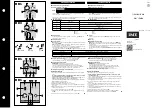
Figure 3. EAFR-101C dipswitch SW1.

3.5 Dipswitch settings

EAFR-101C functionality, such as tripping logic, is configured using 

dipswitch settings .  Different trip configurations can be easily 

programmed by selecting the appropriate dipswitch positions .  This 

gives users the flexibility to change settings dependent on the 

application .  Tripping may be selected based on arc light only or arc 

light and current thresholds .  Current threshold or other tripping 

criteria may be applied to binary input BI1 for blocking a trip caused 

by natural light sources .  Dipswitches 1 and 2 are used as configura-

tion selection .  Dipswitch 3 is for configuring BI5 to operate as a 

Master Trip input or as a current information input .  Dipswitch 4 and 

5 are for setting binary input pairs 1-2 and 3-4 as active or inactive .  

If a circuit breaker is connected to a binary input pair, the respective 

dipswitch should be set to ON .  Dipswitch 6 sets whether trip relay 

outputs T1 and T2 latch or activate momentarily .  Dipswitches 7 and 

8 set whether sensor channels 1/2 and 3/4, respectively, pick up on 

light only or on light and current .
Dipswitches are located at the back of the relay for easy access 

(see Figure 3: EAFR-101C Dipswitch SW1 and Table 2: EAFR-101C 

dipswitch setting selection for details of settings) .

S1/S2 Chan: light

S3/S4 Chan: light

T1/T2: latch

CB1 in use: yes

No

Non-latch

Light and current

Light and current

Configuration select:

8

7

6

5

4

3

2

1

CB2 in use: yes

Master trip

No

Current

Содержание 65C2010G18

Страница 1: ...on 2 2 General 2 3 Operation and configuration 4 4 Arc sensors 7 5 System self supervision 8 6 Application examples 9 7 Connections 9 8 Dimensions and installation 11 9 Testing 12 10 Troubleshooting g...

Страница 2: ...m the point sensor and acting to trip the circuit breaker sourcing the fault current The EAFR 101C complete system self supervision function provides the highest level of dependability by continuously...

Страница 3: ...7 6 13 BI2 X2 12 15 BI1 14 LATCH EN SW6 11 T1 10 LATCH EN SW6 9 T2 8 SF 5 4 3 2 Uaux 1 125 250 Vdc 24 Vdc 24 Vdc 110 220 Vac dc 24 Vdc 12 Vdc 12 Vdc 5 Vdc uP 12 BI4 11 15 BI3 14 10 BI5 9 8 BI6 7 6 BO1...

Страница 4: ...al Verify system condition See Sections 11 Troubleshooting guide and 5 System self supervision T1 and T3 Red Normal status Trip relays T1 and T3 activated N A Check the reason for trip Clear the fault...

Страница 5: ...indications and latched trip relays are reset by pressing the SET button for one second Otherwise the latched trip relays will remain activated until auxiliary power is disconnected All LED indi cati...

Страница 6: ...channel S3 S4 trip criteria Trip on light only L Trip on light and over current L C Both signals are required simultaneously to trip 6 Latch or non latch for trip relays T1 and T2 T1 and T2 operate as...

Страница 7: ...rees Other point sensors are available with different Lux sensitivities EAFR 01 B at 25 000 Lux and EAFR 01 C at 50 000 Lux Figure 4 EAFR 01 arc light point sensor 4 1 1 EAFR 01 installation and wirin...

Страница 8: ...ealthy condition the POWER LED is on and the System Failure SF relay is energized If the self supervision function detects a faulty condition or the power supply fails the self supervision relay is re...

Страница 9: ...ow voltage switchgear 7 Connections Figure 6 EAFR 101C terminals at the rear plate 7 1 Outputs 7 1 1Trip relaysT1 T2 andT3 The EAFR 101C relay has integrated trip relays T1 and T2 for tripping of the...

Страница 10: ...opening operation before the primary contacts part these outputs can be connected to BI1 BI2 or BI3 BI4 If an input is received on either of these two input pairs the EAFR 101C restrains sending any l...

Страница 11: ...ser manual EATON www eaton com 8 Dimensions and installation The EAFR 101C is either door mounted or panel mounted in stan dard 19 in 482 6 mm rack height of 4U and 1 8 of a unit wide Figure 7 EAFR 10...

Страница 12: ...al is utilized verify the BO1 signal activation by the status change of the relevant input where the binary output signal is connected or by measur ing the signal output voltage ote N The BO1 signal i...

Страница 13: ...ns Light only Light current Remarks Sensor channels 1 and 2 setting Sensor channels 3 and 4 setting Object activated LED indication T1 T2 and T3 active BO1 active BO2 active Sensor channel 1 Sensor 1...

Страница 14: ...y for 0 5 s 30 A Make and carry for 3 s 16 A Breaking capacity DC when time constant L R 40 ms 40 W 0 36 A at 110 Vdc Contact material AgNi 90 10 11 4 Binary output BO1 and BO2 Rated voltage 24 Vdc Ra...

Страница 15: ...ulse test voltage Acc to IEC 60255 5 5 kV 1 2 50 us 0 5 J 11 8 Mechanical tests Vibration test 10 to 150 Hz 0 07 mm 003 in 0 5 gn 60 to 150 Hz 10 to 150 Hz 1 gn 10 to 150 Hz Shock bump test acc to IEC...

Страница 16: ...fiber sensor 30 m 93 43 ft EAFR 06 35 65C2013G06 Arc light plastic fiber sensor 35 m 114 83 ft EAFR 06 40 65C2013G07 Arc light plastic fiber sensor 40 m 131 23 ft EAFR 07 10 65C2014G01 Arc light glass...

Страница 17: ...17 Instruction Booklet IB0191002EN Effective November 2019 EAFR 101C arc point sensor relay user manual EATON www eaton com Notes...

Страница 18: ...t between Eaton and the purchaser THERE ARE NO UNDERSTANDINGS AGREEMENTS WARRANTIES EXPRESSED OR IMPLIED INCLUDING WARRANTIES OF FITNESS FOR A PARTICULAR PURPOSE OR MERCHANTABILITY OTHER THAN THOSE SP...

Отзывы: