IOM 570 06/2011
REV A.
Page 5 of 8
E
aton Hydraulics LLC, Filtration Division, 44 Apple Street, Tinton Falls, NJ 07724, www.eaton.com/filtration, Phone 732-212-4700
Installation, Operation & Maintenance Manual
Model 570 Duplex Basket Strainer
HOW
TO
CLEAN
1.
Invert basket and wash out debris by directing a
stream of air or water against the basket exterior.
Use solvent if strained fluid is fuel or a chemical.
Follow manufacturer’s instructions when using a
solvent to clean the baskets.
2.
Inspect basket at each cleaning for holes or tears.
Replace as required. Always keep spare baskets in
stock.
MAINTENANCE:
GENERAL
1.
Inspect baskets at each cleaning for holes or damage.
2.
Replace as required. Inspect body cover seats and
body cover gaskets. Clean seats and replace gaskets
as required.
MAINTENANCE:
LUBRICATION
1.
Lubricate operating mechanism every six months.
Apply heavy grease through the lube fittings located
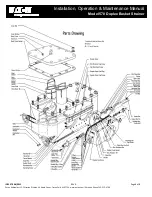
on the operating spindles (see drawing on page 6).
2.
Lubricate chain drive and cover lift mechanism (if so
equipped). Apply light grade grease to moving parts
every three months or as indicated by operating
conditions.
MAINTENANCE:
FLUID
LEAKS
1.
Shut down strainer completely before inspecting
valve discs and valve seats or replacing spindle
mounting O-rings and gaskets, or O-ring nut seals.
2.
Remove header covers only after inlet and outlet
pipeline valves are closed, both cover vents are open
and there is no flow of air or fluid through the vents.
Location of Leak
Correction
Spindle mounting-header
joint
Replace spindle mounting 0-
ring and/or spindle mounting
gasket
Spindle mounting sight
holes
Replace O-ring on O-ring nut
Excessive leakage past
the valve discs
Replace valve seat. Repair or
replace valve disc
HOW
TO
DISASSEMBLE
SPINDLE
MOUNTINGS
1.
Remove spindle-mounting cap screws.
2.
Pull spindle mounting (guide end), including torque bar, out
of header.
3.
Rotate hand wheel counterclockwise to disengage operating
screw from operating spindle. Pull spindle mounting
(operating end), hand wheel and operating screw out of the
header as a unit.
4.
Replace gaskets and O-rings as required.
5.
Reassemble spindle mounting reversing the process used
for disassembly.
6.
Refer to the assembly drawing to be sure components are in
proper order.
HOW
TO
DISASSEMBLE
VALVE
DISC
1.
Remove cap screws and lift cover from header.
2.
Remove disc-retaining bar.
3.
Rotate disc-mounting block out of recess on valve disc.
4.
Attach hoist to valve disc eyebolt. Remove disc through
header opening.
5.
Clean and inspect valve seat and valve disc for scoring or
wear. Wipe with a solvent dampened cloth. Scrape sealing
surfaces if required for examination. Worn or scored valve
seats must be replaced.
6.
Reassemble valve disc to the operating mechanism by
reversing the process used for disassembly.
7.
Refer to assembly drawing to be sure components are in
proper order.


