IOM 570 06/2011
REV A.
Page 2 of 8
E
aton Hydraulics LLC, Filtration Division, 44 Apple Street, Tinton Falls, NJ 07724, www.eaton.com/filtration, Phone 732-212-4700
Installation, Operation & Maintenance Manual
Model 570 Duplex Basket Strainer
RECEIVING,
HANDLING
AND
INSPECTION
1. After unpacking, inspect strainer for damage incurred
during transit. Report any damage to the carrier
immediately. If the strainer is not to be installed
immediately, store indoors in a clean, dry environment.
Replace protective wrap, flange protectors, etc. which may
have been removed during receiving, handling and
inspection.
2. Remove preservative with solvent-dampened cloth.
Exercise care when using solvent and follow solvent
manufacturer’s instructions.
3. Check to be sure the rated pressure and temperature on
the strainer nameplate is not less than the maximum
pressure and temperature of the installation. The rated
pressure shown on the nameplate is the maximum
pressure, including shock, at which the strainer may be
operated.
4. Remove body covers. Check for and remove any foreign or
loose materials that could be carried downstream when
fluid is introduced into the strainer.
5. Be sure shorter baskets are toward the inlet side of the
strainer. Replace strainer cover. Tighten fasteners
uniformly. Baskets are held in place by the pressure of the
cover on the basket handles. If the baskets are loose,
spring the handles to a higher position to insure greater
compression when the cover is seated.
INSTALLATION
CAUTION:
Lift strainer with slings under the
inlet and outlet connections. DO NOT lift the
strainer by the lift eye located on the strainer
cover. The lift eye is used to lift ONLY
the cover.
1.
Position the strainer in the line so that the fluid enters the
connection marked inlet and be sure sufficient headroom
is provided for easy removal of cover and baskets.
2.
Support the strainer in the line as follows. Using the bosses
on the bottom of the strainer, place the unit on concrete
or steel pads. DO NOT support the strainer, or the piping
coming to and from the strainer, by the strainer flanges
and flange bolting.
3.
Connect the strainer to the line. Use the same type flange
faces. For example, DO NOT bolt raised face flanges to iron
INSTALLATION
(
CONTINUED
)
flat face flanges. Iron flanges must be flat face with full-
face gaskets.
4. Cast strainers are subject to face-to-face variations due to
shrinkage and machining tolerances. Prefabricated piping
systems must allow for adjustments to compensate. Be sure
flange gaskets are in place and fasteners are tight.
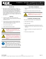
CAUTION:
When strainer handles fluids other
than water and with temperatures in excess
of 120°F, the vent cock must be removed and
the vent piped to a safe discharge point to
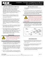
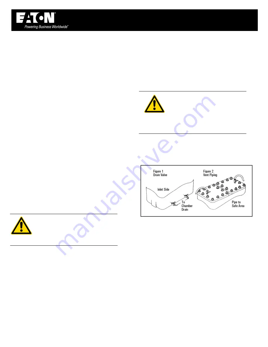
protect the operator (see Figure 2). Wear protective clothing
that includes gloves, vests and goggles when handling
dangerous fluids.
5. An external “equalizer line” is provided between the two
basket chambers. Eaton furnishes the ball valve and piping
components. However, on “suction” applications DO NOT
use this arrangement.
RECOMMENDATIONS
1.
Eaton recommends the removal of the drain plugs on the
outlet side of the body and installation of drain valves as
shown in Figure 1.
2.
Pressure gauges, connected a minimum of four pipeline
diameters from the strainer inlet and outlet, are
recommended.
3.
Cleaning frequency can be determined by the pressure drop
across the strainer. Clean the baskets when there is a 5 PSI
increase in pressure loss across the strainer.


