1
200 A Fused Loadbreak Elbow Connector Replacement Fuse
InstallatIon InstructIons
MN132021EN November 2016
WARNING
Capacitive Test Point Operating Instructions: Use only
voltage indicating instruments specifically designed for
test points . Use of conventional voltage sensing devices
may provide false “No Voltage” indications .
The test point must be dry and free of contaminants
when checking for voltage . After indication is taken:
clean, dry, and lubricate the test point cap with silicone
grease and assemble to the test point .
Always consider the termination to be energized until
the test point “No Voltage” indication is confirmed by
other means . Failure to comply could result in death or
severe personal injury .
WARNING
All associated apparatus must be de-energized during
any hands-on installation or maintenance . Failure to
comply could result in death, severe personal injury and
equipment damage .
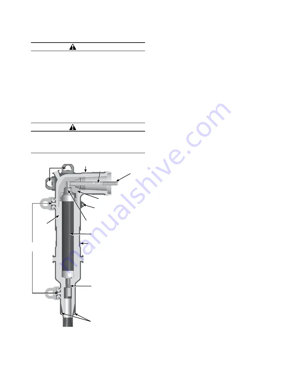
Semi-Conducting Shield
Semi-Conductive Insert
Current-Limiting Fuse
Coppertop Connector
Drain Wire Tab
Loadbreak Band
Probe Adapter
Drain Wire Tab
EPDM
Insulation
Loadbreak Probe
Arc
Follower
Pulling Eye
Test
Point
Figure 1 . Line illustration of 200 A 25 kV Fused Elbow .
Product Information
Introduction
The 200 A, 15 and 25 kV Class Fused Loadbreak Elbow
Connectors from Eaton combines a fully-shielded and
insulated plug-in termination with fullrange current-limiting
fuse protection. The Fused Loadbreak Elbow Connector
provides a convenient and cost effective means to adding
fused protection to underground distribution systems, for
connecting underground cables to transformers, switching
cabinets and junctions equipped with loadbreak bushings.
Read This Manual First
Read and understand the contents of this manual and follow
all locally approved procedures and safety practices before
installing or operating this equipment.
Additional Information
These instructions cannot cover all details or variations
in the equipment, procedures, or process described nor
provide directions for meeting every possible contingency
during installation, operation, or maintenance. When
additional information is desired to satisfy a problem not
covered sufficiently for the user’s purpose, please contact
your Eaton representative.
Acceptance and Initial Inspection
Each current-limiting replacement fuse is completely
inspected and tested at the factory. It is in good condition
when accepted by the carrier for shipment. Upon receipt of
the current-limiting replacement fuse, inspect the connector
thoroughly for damage and loss of parts incurred during
shipment. If damage or loss is discovered, file a claim with
the carrier immediately.
Handling and Storage
If the current-limiting replacement fuse is to be stored for
an appreciable time before installation, provide a clean,
dry storage area. Locate the replacement fuse so as to
minimize the possibility of physical damage.
Quality Standards
ISO 9001 Certified Quality Management System.


