background image

MAINTENANCE, SERVICE AND FAULT FINDING

4-44

25364 Issue 8 March 2018

1024

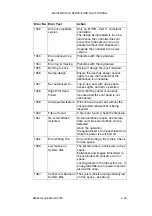
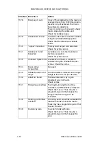
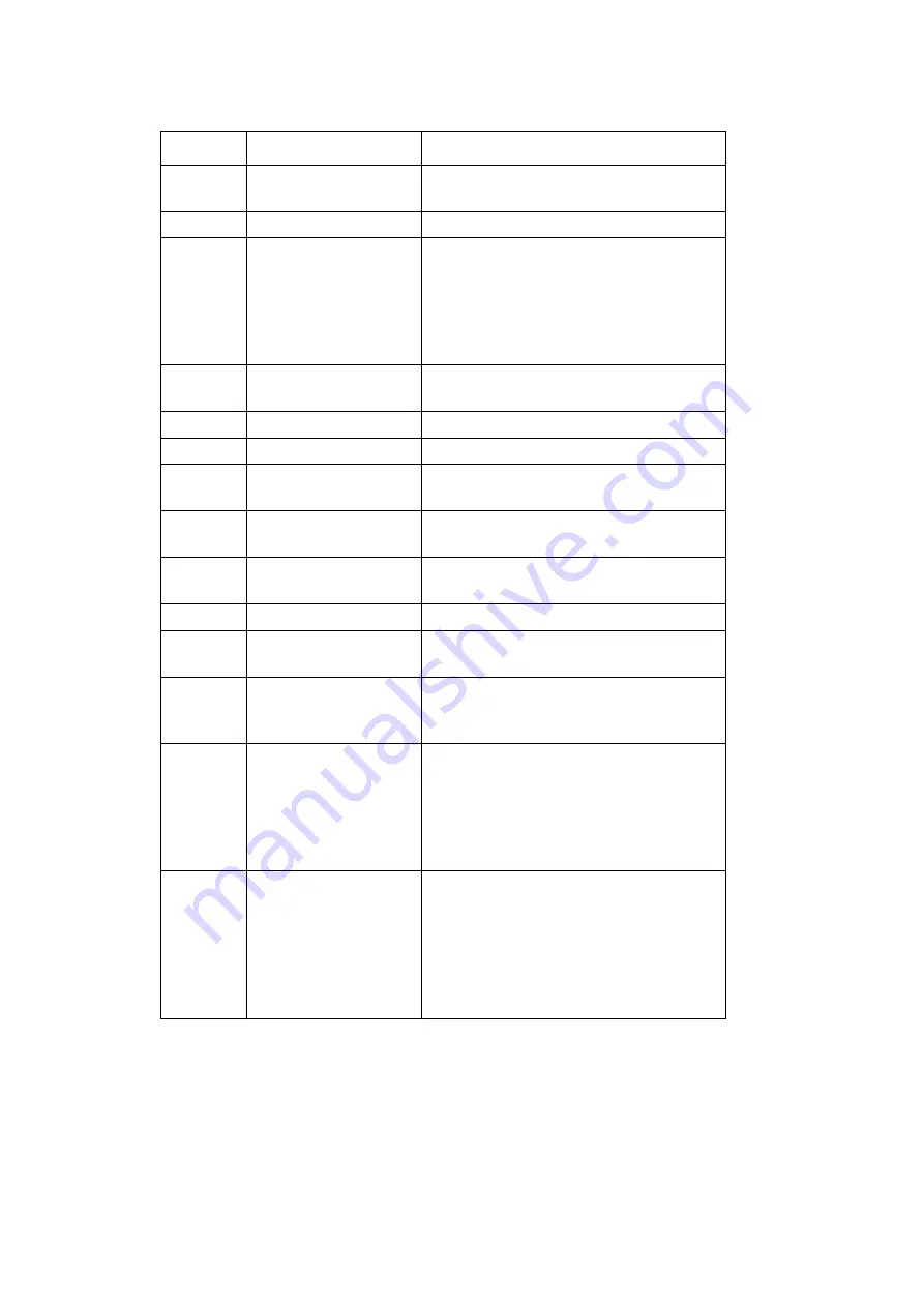
Transfer failed

Retry operation. If problem persists, 
contact service technician.

1025

Not ready to transfer

Contact service technician.

1026

Ribbon Warning

The remaining ribbon has reached the 
limit specified in the Error/Warning 
screen. On the same screen the event 
is set to cause an error.
Check the Error/Warning screen.
Check the remaining ribbon.

1040

Setting out of range

The setting is out of range. Set to 
correct range

1041

Undefined Error

Reserved

1042

Unknown Error

Reserved

1043

Design Pointer Not 
Set

Reserved

1044

Design Delete 
Timeout

Reserved

1045

Label Size Too Big

The label is too large. Edit the design 
and reduce the label size.

1046

No Text Defined Yet

Reserved

1047

Upgrade Failed

Upgrade failed.
Check the Software Versions screen.

1048

Special Action Not 
Found:

Error in firmware/software. Contact 
supplier and supply information on 
how the error occurred.

1049

CRC Error

All files on the controller have a CRC 
checksum. The CRC checksum does 
not match.
Either the file has been modified by an 
unauthorised person, or the file is 
damaged. Contact supplier.

1051

Error incompatible 
version

Only on non-21CFR_Part 11 
controllers:
The design being loaded is too new 
(and hence the controller does not 
know how to handle it).
Upgrade the controller to a newer 
version.

Error No. Error Text

Action

Содержание Communicator II

Страница 1: ...Compact 32d Compact 32C Compact 53c Communicator II Easyprint Product Manual ...

Страница 2: ... 2 25364 Issue 8 March 2018 THIS PAGE INTENTIONALLY LEFT BLANK ...

Страница 3: ...s publication may be reproduced stored on a retrieval system or transmitted in any form or by any means electronic mechanical photocopying recording or otherwise without the prior permission of Easyprint A S Easyprint A S has a policy of continuous product improvement the Company therefore reserves the right to modify the specification contained in this manual without notice Any trademarks referre...

Страница 4: ...VED ANY WARRANTIES REGARDING THE DEVICE OR THE SOFTWARE THOSE WARRANTIES DO NOT ORIGINATE FROM AND ARE NOT BINDING ON MS Note on Java Support The SOFTWARE may contain support for programs written in Java Java technology is not fault tolerant and is not designed manufactured or intended for use or resale as online control equipment in hazardous environments requiring fail safe performance such as i...

Страница 5: ...h all applicable international and national laws that apply to the SOFTWARE including the U S Export Administration Regulations as well as end user end use and country destination restrictions issued by U S and other governments For additional information on exporting the SOFTWARE see http www microsoft com exporting ...

Страница 6: ...8251 The object of the declaration described above is in conformity with the relevant Union harmonisation legislation 2014 35 EU Low Voltage Directive 2014 30 EU EMC Directive 2011 65 EU RoHS Directive EN 61000 6 2 2005 Electromagnetic compatibility EMC Part 6 2 Generic standards Immunity for industrial environments EN 61000 6 4 2007 A1 2011 Electromagnetic compatibility EMC Part 6 4 Generic stand...

Страница 7: ...25364 Issue 8 March 2018 7 EC DECLARATION OF CONFORMITY ...

Страница 8: ...20L05L17G111852 The object of the declaration described above is in conformity with the relevant Union harmonisation legislation 2014 35 EU Low Voltage Directive 2014 30 EU EMC Directive EN 61000 6 2 2005 Electromagnetic compatibility EMC Part 6 2 Generic standards Immunity for industrial environments EN 61000 6 4 2007 A1 2011 Electromagnetic compatibility EMC Part 6 4 Generic standards Emissions ...

Страница 9: ...25364 Issue 8 March 2018 9 EC DECLARATION OF CONFORMITY ...

Страница 10: ...nstruction manual may cause harmful interference to radio communications Operation of this equipment in a residential area is likely to cause harmful interference in which case the user will be required to correct the interference at his own expense Any changes or modifications not expressly approved by the manufacturer could void the user s authority to operate the equipment European EMC Statemen...

Страница 11: ... Issue 8 March 2018 11 CONTENTS PART 1 HEALTH AND SAFETY PART 2 DESCRIPTION AND INSTALLATION PART 3 OPERATION PART 4 MAINTENANCE SERVICE AND FAULT FINDING PART 5 TECHNICAL REFERENCE PART 6 GLOSSARY OF TERMS ...

Страница 12: ...l Parts at Issue 1 November 2010 All Parts at Issue 2 April 2011 All Parts at Issue 3 January 2013 All Parts at Issue 4 April 2013 All Parts at Issue 5 September 2013 All Parts at Issue 6 March 2015 All Parts at Issue 7 November 2015 All Parts at Issue 8 March 2018 ...

Страница 13: ...ling the Compact 32c 53c Communicator II Cassette Printer 1 5 Replacing the Ribbon 1 6 Heating Element 1 6 Organic Solvents 1 6 Battery Replacement 1 6 Fuses Fire Hazard 1 6 Caution Notices 1 7 Damage to Print Head 1 7 Loss of Counter Data 1 7 Cable Routing 1 7 Mains Supply Voltage 1 7 Cleaning Materials for Print Head 1 7 Spare Parts and Consumables 1 8 ...

Страница 14: ...HEALTH AND SAFETY 1 2 25364 Issue 8 March 2018 THIS PAGE INTENTIONALLY LEFT BLANK ...

Страница 15: ...is therefore excludes any phase to phase connected supplies such as may be available in some factories and or countries If the supply fuses located on the rear of the printer and the printer s power supply unit are replaced they must be replaced by a 2 amp T 5x20 UL fuse 230 115V 50 60Hz for the printer and a 4 amp T 5x20 UL fuse 230 115V 50 60Hz for the printer power supply unit V200006 Installat...

Страница 16: ...very care is taken to avoid potential hazards ALWAYS take great care around the machine not to slip trip or fall especially if the machine is used in areas where the floor may be wet or greasy Use only Easyprint ribbons Replace ribbons with care to avoid cutting hands or fingers Take care in the unlikely event of an electronic fault causing an unexpected start up of printer drive motors to avoid p...

Страница 17: ...ator II Cassette Printer Denotes Danger Electricity Denotes General Danger Lethal voltages are present within this equipment when it is connected to the mains supply Only trained and authorised personnel may carry out maintenance work Observe all statutory electrical safety codes and practices Unless it is necessary to run the printer disconnect the printer from the mains electrical supply service...

Страница 18: ...fluid contains organic solvents Always wear suitable PPE goggles and clothes to avoid contact with the eyes and skin Avoid inhalation of the vapour Do not smoke in the presence of the vapour or the vicinity of the printer Replaceable batteries should only be replaced using batteries of the correct specified type and rating Failure to do so may result in an explosion hazard Used batteries should be...

Страница 19: ...e severe damage to the print head The counter values are not retained when the printer is switched off To avoid damage to the cables or equipment ensure that the cables are routed clear from any moving parts To avoid damage to the equipment do not exceed the supply voltage stated in this manual See TECHNICAL REFERENCE on page 5 1 To avoid damage to the printer components use only soft brushes and ...

Страница 20: ...h 2018 Spare Parts and Consumables Contact supplier for details For Sales and Service contact Easyprint A S www easy print com sales easy print com To avoid the risk of damage to the print head use only Easyprint spares parts and consumables ...

Страница 21: ...Box 2 10 MECHANICAL INSTALLATION 2 11 Installation Requirements 2 11 Brackets Compact 32d 32c and 53c 2 11 Mounting the Printer in the Bracket System 2 14 Compact 32d 32c and 53c 2 14 Communicator II 2 15 Connect Cables 2 16 Compact 32d 32c and 53c 2 16 Communicator II 2 17 Set Up Communicator II Printer 2 18 I O Connection Details 2 19 Compact 32d 32c and 53c Pin Allocations 2 20 Communicator II ...

Страница 22: ...er 2 40 ENCODER CONNECTION 2 41 COMPACT TOUCHSCREEN 2 42 Touchscreen 2 43 Touchscreen Rear View 2 44 PRINTER SET UP 2 45 Setting the Ribbon Type 2 45 Threading the Ribbon 2 45 Compact 32d Ribbon Threading Procedure 2 46 Compact 32c 53c Ribbon Threading Procedure 2 48 Communicator II Ribbon Threading Procedure 2 50 Ribbon Path 2 50 Set Up Printer Final Steps Compact 32d 32c and 53c 2 51 Calibrating...

Страница 23: ...g the IP Address for the Compact Touchscreen Touchscreen 2 61 Adding More Connections 2 62 Compact Touchscreen 2 62 Touchscreen 2 63 USB Connection Setup Compact 32d 32c 53c and Compact Touchscreen only 2 64 Reconnecting the Compact Touchscreen via USB Compact 32d 32c and 53c 2 64 ADVANCED SETTINGS 2 65 System Variable 2 65 Special Features 2 65 Install Options 2 66 ...

Страница 24: ...DESCRIPTION AND INSTALLATION 2 4 25364 Issue 8 March 2018 THIS PAGE INTENTIONALLY LEFT BLANK ...

Страница 25: ... and operation of the printer are present Ensure that the following items are present Compact 32d Unit Inventory Contents Part No Compact 32d Printer Unit Compact Touchscreen Optional EAS002781 Mains Power Supply Unit PSU EPP002214SP I O Cable 5m EDP002215SP Documentation Pack Language dependent Compact 32c 53c Unit Inventory Contents Part No Compact 32c Printer Unit Compact 53c Printer Unit User ...

Страница 26: ...2 0 4 and 0 8mm V200042 Wall Bracket PSU Box VEY9984 Wall Bracket I O Box VEY9985 PSU Power Cable Euro VEY0190 PSU Power Cable US VEY0190 1 Air Tube Supply 3m 6mm VEY0786 Cable 4 pole Printer to PSU VEY1404 Cable Printer to I O Box VEY1402 15 Pin I O Cable VEY0168 Ethernet Crossover Cable VEY1420 Documentation Pack Language dependent Secure Digital SD Memory Card VEY0530 Cleaning Pens pack of 5 VP...

Страница 27: ...on Compact 32c 53c USB Port Printer Connections Rear View Rear View Compact 32d shown Rear USB Small Encoder 5 Pin DIN Type Power Input 24V d c 5A Input Output 15 Way D Type Rear USB Large Ethernet cable port to connect to PC or network CAUTION Socket provides Power over Ethernet PoE The rear USB large and rear USB small connections share a port and therefore cannot be used together ...

Страница 28: ...n Parts Printer Unit Front View Cassette Handle Status LED Printer Connections Rear View Secure Digital Flash Card Slot USB Mini Connector Sliding Shutter Air Pressure Gauge Air Pressure Regulator Communication Connector Power Supply Connector Air Outlet Air Inlet USBStandard Connector ...

Страница 29: ...DESCRIPTION AND INSTALLATION 25364 Issue 8 March 2018 2 9 Compact 32d 32c and 53c Peripherals Power Supply Unit Encoder ...

Страница 30: ...icator II Peripherals Power Supply Unit Mains Switch Mains Connector Power Connector Mains Fuse I O Box Encoder Connector Ethernet Connector I O Connector Communication Connector Shims Shim used with the bracket assembly 0 2 0 4 and 0 8 thicknesses available in pack ...

Страница 31: ...ket Brackets Compact 32d 32c and 53c Notes 1 For a list of the tools required see the bracket instructions provided with the bracket kit 2 For spares information see www easy print com The bracket range covers widths of up to 900mm The available flat pack variants are Window bracket for IM and CM versions Notes 1 The CM version includes the encoder and CM axle assembly 2 The CM rubber roller assem...

Страница 32: ...TION 2 12 25364 Issue 8 March 2018 Window Bracket IM Version 0 9m Part No EAS002706 Note Three guide rollers are shown for illustration purposes only two are supplied in the kit Window Bracket CM Version 0 9m Part No EAS002717 ...

Страница 33: ...8 2 13 Web Positioning Module 0 9m Part No 5 0460281 Labeller Bracket Assembly Part No EAS001626 Notes 1 The Labeller Bracket can be assembled in either a left hand or a right hand version 2 Installation drawing EAS002727 is included with the bracket kit ...

Страница 34: ...cket ensure the print head is positioned above the top point of the rubber roller Note To obtain the best print quality fine adjustment of the print head can be done electronically at a later stage See Set Up Printer Final Steps Compact 32d 32c and 53c on page 2 51 3 In order to apply the correct print head pressure ensure that the height between the base of the printer and rubber roller or platen...

Страница 35: ... top point of the rubber roller This may be adjusted to obtain the best print quality 2 Adjust the height between the rubber roller or platen using the appropriate shims provided Note The height may need to be adjusted once the services are connected Fitting Shim between the Bracket and Printer 3 When the correct distance is obtained tighten the screws Mount the I O box and power supply See Connec...

Страница 36: ... the Compact Touchscreen s mini USB port then connect USB A into the USB port on either the front or the back of the printer If a retained connection is required between the Compact Touchscreen and the USB cable the mini USB plug lead can be secured in place by removing the rear cover of the Compact Touchscreen and fitting a small cable tie to the mini USB plug If a retained connection is required...

Страница 37: ... Connect the printer cable between the printer and the I O Box Connect the air pressure to the printer Set the regulator to approximately 2 5 bar 0 25MPa 128mm Printer 3 5 Bar 0 35MPa so that the air pressure gauge reads either 2 5 Bar or 3 5 Bar Supply the mains to the Power supply Connect the I O to the host machine If the printer is used in CM connect the encoder to the I O box If a Touchscreen...

Страница 38: ...rom the Line Movement pull down menu 1 If you select the CM printer type a To check that the print head is on top of the roller go to Settings Production Line Setup Print Head b Set the Head Position so that the print head is on top of the roller Note Some experimentation with this parameter may be required to obtain the best print quality c Perform a print run d Go to Settings IO Port Set Up Star...

Страница 39: ...tput Volt free contacts These contacts are operated and driven by a relay on the printer circuit board They are normally open or normally closed depending on the assigned function They serve as a switch operated by the printer to output its status 2 Input Volt free contacts Their main function is to provide the start signal for printing These contacts can be operated by a switch connected to the p...

Страница 40: ...icated on 5 pin DIN 8 15 Purple Red White Input 2 Volt free contacts Start Signal 5 13 Yellow Black White Input 3 Volt free contacts None 6 14 Green Brown White Input 4 Volt free contacts Remote Trigger Front Multi Function Button Function cannot be changed 7 15 Blue Red White The volt free output contacts are each capable of handling a load of 30V 100mA The function of each output can be changed ...

Страница 41: ...art Signal 5 13 Yellow Black White The function of each output can be changed in the software the defaults are listed in the table see page 2 28 for descriptions For more information regarding configuration of inputs and outputs see Inputs Outputs on page 3 52 By default Output 1 and 2 are volt free contacts they can be changed to NPN contacts by 1 Open the I O box by removing the 2 screws on the ...

Страница 42: ...owered contacts is set by JP1 and JP2 on the connection board as follows JP1 and JP2 Position Output Voltage Pin 9 Maximum Current 1 2 5V 100mA 2 3 24V 500mA Both jumpers must be moved Communicator II Pin 9 provides 5V max 100mA and ground is on pins 10 13 14 and 15 with the I O box jumpers fitted in the default position If the I O box is changed from volt free to NPN outputs then pins 11 and 12 c...

Страница 43: ...nd 13 of the I O connector as shown in the following diagram Pin 5 Yellow Pin 13 Black White Printer Relay Alternative Start Signal Yellow 5 Black White Yellow Black White Yellow Black White 5 5 13 13 13 VCC_ISO VCC_ISO VCC_ISO GND_ISO GND_ISO GND_ISO U4 U4 U4 H11L1M H11L1M H11L1M Relay R15 R15 R15 1K 1K 1K Start signal Start signal Start signal 1 1 1 2 2 2 6 6 6 4 4 4 5 5 5 Open Collector open Dr...

Страница 44: ...ulti function button can be triggered with a 1 second pulse which will either tension the ribbon initialise the printer or clear error depending on printer status An 8 to 10 second pulse will switch off the printer The connection is made using pins 7 and 15 of the I O connector as shown in the following diagram Pin 7 Blue Pin 15 Red White Printer Relay ...

Страница 45: ...1 and JP2 on the connector board are set to the default position 2 3 for 24V See Output Voltage page 2 22 2 Connect the NPN sensor as follows 24V Pin 9 0V Pin 13 Signal from sensor Pin 5 Pin 5 Yellow Pin 13 Black White Printer Pin 9 Grey Sensor Signal 24V 0V Communicator II 0V NPN Sensor 24V Signal I O Box Pin 5 Pin 13 24V Power Supply 24V 0V ...

Страница 46: ...ree contacts with a maximum loading of 30V 100mA Output 4 is a powered contact Pin 9 is supplied with 24V by default See the pin allocation table on page 2 20 Pin 12 Light Green Pin 10 White Pin 4 Orange Pin 2 Brown Pin 11 Pink Pin 3 Red Printer Output 1 Output 2 Output 3 I O Connector 15 pin D Type Output 4 Pin 9 Grey Pin 1 Black ...

Страница 47: ...ommunicator II Pin Allocations page 2 21 The output should be connected as per the diagram below Light Green Orange Pink Red External Relay 3 11 4 12 Relay 24V Error Ready The internal switch for the output signal can handle a maximum of 30V and 100mA The internal switches pull down the signal level to ground Therefore it is very important to mount pull up resistor s and or a relay s CAUTION Never...

Страница 48: ...ad is in printing position and closed while head is not printing Ready Printing Contacts closed when printer is ready and printing open while returning in IM mode Ready Returning Contacts closed when printer is ready and returning open while printing Ready Printing Returning Contacts closed when printer is ready and printing returning in IM mode Error Contacts open when an error is active Error in...

Страница 49: ...s will not be shown on the home screen 2 When the switch is closed the printer is paused when the switch is open the printer will resume 1 Select 2 available pins from one of the tables bellow and connect the switch Compact 32d 32c 53c and Communicator II Pins Colours 5 13 Yellow Black White 8 15 Purple Red White Compact 32d 32c and 53c Only Pins Colours 6 14 Green Brown White 2 Select Settings IO...

Страница 50: ...nnector The encoder can be connected to Input 1 of the I O Connector which duplicates the encoder connector 1 Ensure printer supplies 5VDC on pin 9 see Output Voltage on page 2 22 2 Connect Pin 15 Red White to Pin 3 Blue of Encoder 0V Pin 8 Purple to Pin 2 White of Encoder Signal Pin 9 Grey to Pin 1 Red of Encoder 5V ...

Страница 51: ...DESCRIPTION AND INSTALLATION 25364 Issue 8 March 2018 2 31 I O Wiring Diagrams Compact 32d 32c and 53c ...

Страница 52: ... I O_OUT2 R12 1K R13 1K 1 2 3 4 8 7 6 5 LH1250AAC IO_OUT1 IO_OUT1_RET IO_OUT2 IO_OUT2_RET DEFAULT LINK POSITION IO_OUTn_RET GND_ISO LINK PINS 1 and 2 GND LINKAGE SELECTION DEFAULT SEPARATE GND and GND_ISO LINK PINS 1 and 2 JP2 JP3 JP1 3 2 1 3 3 2 2 1 1 JUMPER JUMPER JUMPER LK1 LK2 LK3 PLACE CLOSE TO J4 PLACE CLOSE TO J4 16 or 17 IO_OUT1_RET IO_OUT2_RET IO_OUT1 IO_OUT1_RET IO_OUT2 IO_OUT2_RET I O_I...

Страница 53: ...Ethernet cable port to connect to PC or network 2 CAUTION Socket provides Power over Ethernet PoE Compact Touchscreen to USBA Mini USB1 Packaging Machine I O Cable P N EDP002215SP Notes 1 The rear USBA and Mini USB connections share a port and therefore cannot be used together 2 To connect the printer to a network see Compact Touchscreen to One Printer Compact 32d 32c and 53c on page 2 35 To conne...

Страница 54: ...ean Air Supply Rear View Cable VEY1414 Euro VEY1415 US Touchscreen To Network Packaging Machine I O Shaft Encoder I O Box Power Supply Cable VEY1404 Cable VEY0190 Euro VEY190 1 US Air Tube VEY0786 Cable VEY1402 Cable VEY0168 Laptop Net worked PC Ethernet Switch Router Crossover Cable EPT007719 Crossover Cable VEY1420 ...

Страница 55: ...ped between many printers Direct USB Connection No Network Compact Touchscreen Touchscreen PC to Networked Printers CAUTION Power over Ethernet Risk of equipment damage Use optional adapter cable EPT031606 to provide a DC block if the network equipment is susceptible to damage by Power over Ethernet from the printer An example network diagram follows in which a Compact Touchscreen Touchscreen or P...

Страница 56: ... required which will need to be purchased locally Network Set up Refer to Printer Network Settings on page 2 38 for details on the printer network settings Connecting to Networked Printers Refer to the example network diagram on page 2 35 To log on to a powered on printer 1 Upon powering on the Compact Touchscreen Touchscreen select the desired printer from the list of available printers 2 If disp...

Страница 57: ... Compact 32d 32c and 53c Crossover Ethernet Cable Note Initially ensure both printer and PC are DHCP enabled Then if required set the IP settings for the printer and PC Touchscreen Communicator II To connect a Touchscreen see Connectivity Communicator II on page 2 34 Crossover Ethernet Cable ...

Страница 58: ...lt settings are as follows Enable DHCP DHCP is NOT enabled by default Printer IP address 192 168 125 201 Touchscreen IP address 192 168 125 200 Printer Slaves The Printer Slaves function allows one printer to control up to 10 other networked printers performing the same task The user can also add or remove a slave printer as well as edit the details of an existing printer To employ the master slav...

Страница 59: ...he tickbox if left unticked the slave setting will remain inactive Advanced It is possible to access a remote database this allows data such as product name barcodes etc to be retrieved and used within messages Name Enter the IP address or host name of the PC or Server where the database is located Port Enter the port location at which the ODBC resides normally 701 ODBC Active Tick or untick the b...

Страница 60: ...fari from version 6 To connect 1 Connect the PC and Printer directly via Ethernet connection See PC or Touchscreen to One Printer on page 2 37 Or through a network connection See Compact Touchscreen Touchscreen PC to Networked Printers on page 2 35 2 Power on the printer and start the PC 3 Start the PC web browser application 4 Enter http IP address of the printer in the address field of the web b...

Страница 61: ...ON 25364 Issue 8 March 2018 2 41 Encoder Connection The Shaft Encoder connection when the printer is used in CM is shown Shaft Encoder Connections to the Printer NPN 1 RED 5V 2 WHITE SIGNAL 3 BLUE 0V 3 5 2 4 1 ENCODER CONNECTION ...

Страница 62: ...he USB port of the Compact Touchscreen If this is a requirement use a powered USB hub If a retained connection is required between the Compact Touchscreen and the USB cable the mini USB plug lead can be secured in place by removing the rear cover of the Compact Touchscreen and fitting a small cable tie to the mini USB plug The Compact Touchscreen USB cable supplied is 2m in length A maximum cable ...

Страница 63: ... a powered Ethernet port This can be used to power the Touchscreen without additional power cables Contents Part No Optional Touchscreen with European mains lead and crossover Ethernet cable EPT007715 Optional Touchscreen with US mains lead and crossover Ethernet cable EPT007714 European Power Cable VEY1414 US Power Cable VEY1415 Cable to I O box Ethernet EPT007719 Touchscreen LCD Panel ...

Страница 64: ...witch Communication Port USB Ports Plug the crossover cable into the I O box Connect the mains cable to the Touchscreen Connect the crossover cable to the Touchscreen Turn on the power to the Touchscreen Select the printer to connect to and log in if required Open the Message Store Highlight a design Press Print ...

Страница 65: ...aken when replacing threading ribbons to avoid cutting hands or fingers Notes 1 To ensure good quality print always clean the print head and capstan before fitting a new ribbon to the printer 2 When fitting a new ribbon ensure loose ribbon is wound up on the take up spool to create tension in the ribbon path If this is not done the ribbon will not be fed correctly around the guides and rollers in ...

Страница 66: ... ing Arm Dancing Arm Bridge Cover Ribbon Threading Compact 32d Right hand Printer Ribbon Guide Roller 1 Rotate the quarter turn latch anti clockwise Gently pull the printer s front cover straight out towards you to remove it 2 Fit the new ribbon roll on the unwind spindle and the empty core to the rewind spindle 3 Open the dancing arms to aid ribbon threading ...

Страница 67: ... and thread the ribbon accordingly Compact 32d Ribbon Path Left Hand Compact 32d Ribbon Path Right Hand Note To change the printer from left hand to right hand or vice versa see Changing Printer Configuration on page 4 24 5 Wrap the ribbon around the empty ribbon core several times taking up any slack in the ribbon path to complete the operation Flip the dancing arms back to the closed position 6 ...

Страница 68: ...as either a right hand printer or a left hand printer Referring to the ribbon path diagram labels on the printer cover or in the following diagrams determine whether the printer is set up for left hand or right hand printing and then thread the ribbon round the dancing arms according to the appropriate diagram Left Hand Compact 32c 53c Ribbon Path Right Hand Note To change the printer from left ha...

Страница 69: ...Printer open 6 Fit the cassette to the printer 7 Push the latch closed to lock it CAUTION If the latch is forced closed before the cassette is fully inserted it may become damaged 8 Press the reset button The printer initialises Note If an audible clicking or banging noise is heard during calibration the ribbon is threaded incorrectly Remove the cassette to halt the calibration Review the ribbon p...

Страница 70: ...ler Ribbon Path label 1 If fitting a replacement ribbon remove the used roll and discard re use the inner core if needed 2 Fit the new ribbon roll on the unwind spindle and the inner core to the rewind spindle 3 Thread the ribbon as shown on the ribbon path label fitted to the cassette assembly See overleaf 4 Wrap the ribbon around the empty ribbon core several times taking up any slack in the rib...

Страница 71: ...oduction line See below 2 In dusty environments it may be beneficial to fit a V Series Positive Air Kit P N EAS002970 Calibrating the Printer CAUTION When calibrating the print head must be able to extend fully please ensure enough space is allowed to perform this function In CM the print head position parameter must be set to allow this in IM the printing surface should be moved from under the pr...

Страница 72: ... Speed is updated every few seconds 2 For Compact 32d 32c and 53c printers Go to Settings Production Line Setup Head Functions and use the Align button to automatically set the head position to the roller If necessary manually adjust the Head Position and Print Head Height parameters to set the correct distance of 0 2 2mm between the print head and substrate for both CM and IM 3 Review the followi...

Страница 73: ...t the Print Trigger as required at Settings Production Line Setup Print Trigger For more information see Print Trigger on page 3 49 5 Go to Settings Production Line Setup Print Head and set the Head Position a For the CM printer type set the Head Position so that it is above the roller b For the IM printer type we recommend that the horizontal print head position is set to 0 ...

Страница 74: ...fast optimisation and fault finding on the TTO printers 1 Connect to a printer 2 Ensure a label is loaded to print 3 Press Home Settings Production Line Setup Speed Profile A blank graph should be visible The Settings button allows you to set up the following X Axis Time or distance X Axis Sample length in mm or ms as selected above Trigger by Either trigger on print go or set to run until an erro...

Страница 75: ...N 25364 Issue 8 March 2018 2 55 CM Speed Profile Graph 1 2 4 3 1 Substrate speed 2 Ribbon Speed 3 Printing 4 Print Go It may be necessary to scroll up down and left right to see the full graph Press Refresh to repeat the capture ...

Страница 76: ...N 2 56 25364 Issue 8 March 2018 IM Speed Profile Graph 2 1 4 3 1 Printhead speed 2 Ribbon Speed 3 Printing 4 Print Go It may be necessary to scroll up down and left right to see the full graph Press Refresh to repeat the capture ...

Страница 77: ...2 Select Unlock UI Settings 3 Enter the password QS and select To lock the user interface settings select Lock UI Settings Printer Connection Set up the method of connection between the Compact Touchscreen Touchscreen and printers Select one of the following Connection Methods to connect the UI to the printer s Broadcast Use this option if the Compact Touchscreen Touchscreen is to be used with mul...

Страница 78: ...ated with this approach For example When a printer or a Compact Touchscreen is assigned an IP address by the network it will use this address until powered down However when the device is powered up again there is no guarantee that it will get the same IP address If a PC based interface running a standard browser such as Internet Explorer is used re establishing a connection is not straightforward...

Страница 79: ...ndows 7 version 4 1 or higher ActiveSync can be downloaded from Microsoft homepage USB cable with mini USB at the printer end Connecting Turn on the printer Wait 45 seconds Ensure that the standard USB connector at the rear of the printer is not being used Use the mini USB cable to connect the PC to the printer s mini USB connector as shown in the following images Mini USB port Compact 32d 32c and...

Страница 80: ...esh once as the folder is sometimes not updated 3 Copy the IP_Address txt file to the PC s hard drive 4 Use Notepad to open the IP_Address txt file now located on the PC 5 The file shows the IP address that was used during the last connection 6 Remove USB cable if no further connection is required Change IP Address of Printer Using USB 1 Navigate by using Explorer in ActiveSync to the Flash Disk f...

Страница 81: ...lock User Interface Settings on page 2 57 To change the IP address of the Compact Touchscreen Touchscreen when it is running from an external PSU 1 Select Settings User Interface Network 2 Select the Hostname 3 Untick the Enable DHCP tickbox 4 Change the IP Address which changes immediately Note For Compact 32d 32c and 53c only If the default server IP address of the Compact Touchscreen is changed...

Страница 82: ...pact Touchscreen is not connected via USB to any printers but is powered by the optional power supply and connected to the network via an STP ethernet cable 3 Ensure that the Compact Touchscreen s IP address is set correctly 4 Select Settings Printer Connection Connection Method and choose one of the following connection methods Broadcast Select Broadcast to display a list of detected devices on t...

Страница 83: ...enu and select Refresh Direct If the device s connection details are known select Direct Add Direct Enter the Name Type IP Address Port Host and select OK If the devices connection details are not known select Direct Add Direct Get from Broadcast Choose from the list of detected devices on the network Favourite Create a list of favourite printers If the connection details are known select Favourit...

Страница 84: ...of the printer for example 6 Select Type and choose TTO from the drop down menu 7 Select IP Address and enter 169 235 97 135 8 Select Port and enter 700 9 Select Host and enter the host name of the printer This value will be displayed next to the IP address of the printer on the Compact Touchscreen connection screen The value entered is not used for connection Reconnecting the Compact Touchscreen ...

Страница 85: ...the printer It is this name that defines the machine ID identity which can be used as a variable in a message Note Do not confuse the machine ID with the host name Special Features This tab shows the System ID Note Feature Codes such as Continuous Head Down Override Max Contrast Override Print Position or SD Emulator can be added or removed ...

Страница 86: ...hange the setting set or remove the tickbox and perform a mandatory reboot of the printer To verify if Complex Scripting is enabled a design with some Arabic text is required When Complex Scripting is enabled the text is correct When it is disabled it is incorrect Auto Copy Designs If a USB device containing design files stored in the root directory is inserted into the printer the user is asked i...

Страница 87: ...DESCRIPTION AND INSTALLATION 25364 Issue 8 March 2018 2 67 ...

Страница 88: ...DESCRIPTION AND INSTALLATION 2 68 25364 Issue 8 March 2018 THIS PAGE INTENTIONALLY LEFT BLANK ...

Страница 89: ... 8 STATUS BAR 3 8 MESSAGES 3 10 NEW MESSAGE 3 11 Add 3 11 Text 3 12 Variable 3 14 Clock 3 14 Counter 3 18 Prompted Field 3 19 Link 3 19 External Data 3 20 Database Content 3 22 Printer Data 3 22 Shift Code 3 22 Edit Variable 3 23 Properties 3 23 Barcode 3 24 Shape 3 27 Image 3 27 Copy Clone 3 27 Move Size 3 28 Rotate 3 28 Zoom 3 29 File 3 30 Save Message 3 30 SELECTING AN EXISTING MESSAGE 3 31 Edi...

Страница 90: ...0 Heater State 3 50 Print Head Set Temp 3 50 Print Head Resistance 3 50 Print Head Height Compact 32d 32c and 53c 3 50 Head Position 3 50 Head Position Offset 3 51 Head Functions 3 51 INPUTS OUTPUTS 3 52 Assignment 3 52 Monitor 3 52 Test 3 52 REGIONAL SETTINGS 3 53 Language and Keyboard 3 53 Date and Time 3 53 FILE MANAGER 3 54 Printer 3 54 Local 3 54 Create a Message Store on the Printer 3 54 Cre...

Страница 91: ... Enable the SD Emulator 3 58 Connect to the Printer Using CoLOS Create 3 58 Use Messages Designed for SD 5 X40 or X60 3 59 Download a File to the Printer 3 59 Request a Message at the Printer 3 59 Setting the Host PC Mode in CoLOS Create 3 59 Allocating a Job Source to a Printer 3 60 ...

Страница 92: ...OPERATION 3 4 25364 Issue 8 March 2018 THIS PAGE INTENTIONALLY LEFT BLANK ...

Страница 93: ...ally powers on b If connection is via Ethernet the Compact Touchscreen powers on when the USB power cable is connected or when the Touch screen is turned on 2 If the connection is via Ethernet the Connection screen displays either a Select the device to connect to or b Long press the device name for details and then select either Connect or Cancel 3 Enter Username and Password if requested the Hom...

Страница 94: ...ettings and Settings as shown below Home Screen Menus Long press to Access Security Management It is possible to configure the third button Global Print Settings in the example above Go to Settings and long press the desired Menu At the prompt Would you like this button to appear on the Home screen select OK to confirm or Cancel ...

Страница 95: ...og Off Disconnect from Printer Main Screen Area For more information see STATUS BAR on page 3 8 Editor Screen Vertical Scroll Select Item Redo Undo Breadcrumb Trail Menu Buttons Sub Menu Lock Screen Log Off Disconnect from Printer Notes 1 Long press can be used on most buttons to view a short description of the button s function 2 When an icon is greyed out its function is not available from that ...

Страница 96: ...e LED changes colour then release the Reset button To shut down the Communicator II printer turn off the switch on the power supply STATUS BAR Status Bar Play Stop Button The Status Bar s colour denotes the printer s status whilst the Play Stop button enables the user to select a new print state for an active message For example if a message is selected and the Status Bar shows Ready select the Pl...

Страница 97: ...se Print the Status Bar turns blue and displays Paused Select the Play Stop button to select a new state If no message is selected the message field displays No message selected The Status Bar is blue and displays Idle and the Play Stop button is not visible ...

Страница 98: ...een above the message store called Internal and a list of messages it contains are displayed Select any saved message from within a message store or from the list of messages You can then edit preview cancel or send the message to print To edit a message while it is printing go to Home Screen Messages and select Edit Printing Message ...

Страница 99: ...us action 2 To see a brief description of a button long press the button 3 It is possible to select the message area to locate the cursor adding an item will then place the item at the cursor point Add Add various items into the message Text Text Variable Clocks etc Barcode Barcode Variable Line Shape Image Items Available to Add into a Message Clone Item Notes 1 When an icon is greyed out its fun...

Страница 100: ...Available Keyboard Languages Clear the Text Field Delete Previous Character To add lines of text into the message enter text into the Text Area and select Enter It is also possible to include variables such as clock information within a text item If required select the variable button select the variable from the list or create a new variable Alternative characters are available via the Unicode IM...

Страница 101: ...haracters are added select to include the text item in the message Selecting the will revert to the Add menu without adding the text item into the message IME Input Method Editor in a similar manner to entering Unicode characters above select the button to display the IME entry area the button will change to amber Enter the required characters Select again to revert to the text screen Once all cha...

Страница 102: ... three letter abbreviation dddd Day of week as its full name M Month as digits with no leading zero for single digit months MM Month as digits with leading zero for single digit months MMM Month as a three letter abbreviation MMMM Month as its full name y Year as last digit with no leading zero for single digit year yy Year as last two digits with a leading zero for years less than 10 yyyy Year re...

Страница 103: ... character time marker string such as AM or PM Supported Special Formats Value Description JJJ Day of year always three digits 29th of February 060 WW Week of year always two digits The first 4 day week in the year 01 D Day of week Sunday 0 Monday 1 Saturday 6 Language To define the date or month with letters this menu allows a choice of various languages English Spanish Finnish Italian Example No...

Страница 104: ...in a calendar format The time printed will be the fixed date in place of the variable clock Certain parts of the prompt can be customised 1 Open the message in the editor 2 Click Message Orphaned variables Edit Variable and edit the variable corresponding to the date picker Here you can set the text of the prompt and if the last used value is retained Offset When a clock is required showing an ear...

Страница 105: ...e If the clock is required to be updated after every print this box must be activated Printing speed will not be affected if this option has been selected Specify Time Day and time can be specified for when the variable should be updated This is done by going back to the specified day and then calculate the offset Actual day is Wednesday Update should be done on Mondays The variable will update th...

Страница 106: ...the name of an already used variable is changed the items in which the variable is used must be manually updated Output Use the drop down menu to choose a numerical system for the output The following numerical systems are available Numeric Hex Alpha AlphaNumeric and Arabic Padding use the drop down menu to choose between Leading Zeros or Leading Spaces to fill spaces in the number string Prompt P...

Страница 107: ...lowing properties are available for editing Input Type Select AlphaNumeric to enter letters and digits or Numeric to enter only numerical values Length The maximum number of letters is set here For example if it is known in advance that all answers consist of a maximum of eight digits then only enter a maximum of eight digits Name The name of the variable is entered here Selecting the Name tab wil...

Страница 108: ...rd for example SOH ETB STX and ETX 2 vNN NN characters to be printed 3 dNN NN characters as don t care 4 Clear text There must be a direct match between the text and the info that the device sends NN is to be considered a number in the range from zero to 255 typed in as hexadecimal For example to denote the number 77 decimal type in 4D hex Example The printer expects data in the following format S...

Страница 109: ...s used must be manually updated Updating This variable can be set up in one of five ways 1 On Request When the value is sent the variable is updated and printing will continue with this value until a new value is sent 2 Each Print A new value has to be sent for each print buffer capacity 1000 Values 3 Each print No Buffer A new value has to be sent for each print 4 First Time Only One and only one...

Страница 110: ...th If no database is connected follow the on screen prompts to establish a connection For more information see Advanced on page 2 39 Printer Data Add the Printer ID or User ID to the message Shift Code Create or edit shift code data within the message The following properties are available for editing Name The name of the variable is entered here Selecting the name field will call up a keyboard wh...

Страница 111: ... variables contained is displayed select from the list to edit or select to delete from the list Properties To view a message item s properties select the item within the message and long press it To edit an item s property select its text field or pull down menu enter or select the desired data and select to confirm ...

Страница 112: ...select the button to insert the code into the message To display edit properties either Highlight the barcode within the message and select the More button OR Select and long press the barcode to find its properties Text Area To delete a message s selected item whilst in the barcode s Properties screen select the Delete Item button Using the Move Size and Rotate Flip functions arrange the item as ...

Страница 113: ...ck web material this way the barcode will still look normal for a barcode scanner Anchor Each item is surrounded by a virtual rectangle The anchor point determines where the x and y coordinate touches this rectangle The anchor point is also used as the point of orientation The default is Top left Top Left Top Centre Top Right Centre Left Centre Right Centre Bottom Left Bottom Right Bottom Centre S...

Страница 114: ...et in points Position X mm Defines the x position across the print head of the item Numerical values can be entered Position Y mm Defines the y position longitudinally with the print head of the item Increasing this value moves the item in the writing direction Numerical values can be entered Rotation Used to select the desired rotation the item can be rotated to 0 90 180 and 270 In combination wi...

Страница 115: ...folder stored in the printer Either Browse for the required image or Go to Settings File Manager Printer and select USB drive to view the images on the USB drive Import an image from either the USB or a remote source by entering the pathname of the image s location Note Imported images must be monochrome bmp format Using the Move Size and Rotate Flip functions arrange the item as required within t...

Страница 116: ... in the message Select the item s box to resize then using the resize buttons make the box larger or smaller as required or Select the item s box select and hold the small red rectangle note it will turn yellow then drag the corner out to resize it Note The resize buttons will only resize the entire item box To change the font size of the item select the item and then the button Rotate Once an ite...

Страница 117: ...sage field or the whole Message field in a different size select the item s and then select the appropriate button from the above toolbar 1 Incrementally zoom in on the message area 2 Incrementally zoom out of the message area 3 Fit whole message height to area 4 Fit whole message width to area 5 Zoom to 100 actual size of Message 6 Zoom selected item to fit into message area ...

Страница 118: ...e 3 Save as a new message 4 Add or edit a connection to a database 5 Add new Shift Code table 6 View edit variable properties 7 View edit the message properties 8 Delete item from message 9 Send to print Save Message Once the message has been created changed select the Save Button to save the message Enter the message name required and select the message store if appropriate ...

Страница 119: ...wing screen will display Choose to Edit Preview Send to Print or Cancel To change the selected message select Messages then open the required message store and select the required message The screen as shown previously will display select Send to Print The printer will revert to the Home screen and the selected message will be displayed Edit To edit an existing message 1 Select Messages and select...

Страница 120: ...erties menu 5 The message can now be edited using any of the following edit functions 1 2 3 4 5 6 7 8 9 11 10 1 Display Keyboard 2 Display Change Font Size 3 Select Font 4 Bold 5 Italic 6 Underline 7 Text Alignment 8 Display Change Line Spacing 9 List All Settings 10 Clone Item 11 Delete Notes 1 The Edit functions are the same for new messages 2 Available functions vary depending on message conten...

Страница 121: ...ode items The Properties area will be open as default Dimensions and location details can be changed as well as rotation font and italicisation Select the Add Text button to open the keyboard and amend the content Select the Add Variable button to add a variable into the item either select from the list or create a new variable Select the Edit Variable button to edit or remove variables within the...

Страница 122: ...ls the contrast at which the print head prints The recommended settings for this are between 80 100 Higher values require more energy when printing The contrast required is dependent on the type of material being printed on and the type of ribbon used for printing If a low quality ribbon is used it may be necessary to increase the contrast but the life of the print head will be considerably reduce...

Страница 123: ...sure controls the pressure that is applied to the print head during printing The pressure required is dependent on the type of material being printed on The default value is 1 0 bar This value will need to be reduced if the ribbon economy function is being used and may need to be increased if printing onto rough surfaces such as paper labels Note When increasing the level of ribbon economy it is n...

Страница 124: ...in this menu but if increasing the Ribbon Economy reduce the contrast and head pressure settings accordingly thus increasing the lifetime of the print head An example of what a used ribbon and the actual print looks like if a value of 60 has been entered in Ribbon Economy Ribbon Economy set to 60 Note A high head pressure will cause the web to drag the ribbon due to friction and can cause a floppi...

Страница 125: ... this may be due to having selected the YES mode and the print head and the ribbon does not have sufficient time to lift up return or to accelerate and decelerate Reduced print quality in the middle of the design at high speeds could be due to this option being set to YES Retraction Type CM only This setting is very important in reducing consumption of ribbon The thermal transfer printer normally ...

Страница 126: ...alue causing prints to overlap on the ribbon Retraction Length CM only The way in which this field is displayed on the screen depends on how Retraction Type has been set If it is set to off the field is greyed out If Retraction Type has been set to Auto Retraction Offset must be set in this menu If Retraction Type has been set to Manual Retraction Length must be set in this field Retraction Offset...

Страница 127: ...nt across the substrate will change Column Mode is particularly useful when the message to be printed is significantly narrower than the ribbon width and where the printed position of the code across the ribbon is allowed to vary Column Mode can also be used with the Ribbon Retraction and Ribbon Economy features However Column Mode has some limitations and cannot be used if The appropriate length ...

Страница 128: ...ays the same as the width of the print as the width of the print may be smaller Usually Column width Print head width Number of columns However this parameter must be a whole number So in the preceding example using a 53mm print head Column Width 53 5 10 6 10 Position The following settings can be adjusted or set from this tab X Offset Displaces the print across the print head By entering a negati...

Страница 129: ... signal from the packaging machine sending signals in the middle of printing Note The offset is defined in mm millimetres in CM and in ms milliseconds for IM In the following example the print would normally be interrupted by the second signal with the result that the printer will only print every other print By setting Delay Type instead the printer will not be interrupted in the middle of printi...

Страница 130: ...t Technical The Printer uses default settings for the application Settings can be manually adjusted Head down For Compact 32d 32c and 53c printers When the print head needs be lowered i e at the start of a print the printer s software sends a signal to the twin shafted motor thus lowering the print head For Communicator II printers An air valve controls the printer s print head movement When the p...

Страница 131: ...g Motor start offset CM only This defines when the stepper motor should start pulling the ribbon relative to the start of the print To obtain good quality print the ribbon should be moving when the print head is lowered If the ribbon is not moving when the print head is lowered a black line may occur at the start of the print The default setting is sufficient in most applications At extremely high...

Страница 132: ...once printing is complete you will be prompted to select the next action The Action When Done pull down menu allows the user to select the next action when the count is completed Available actions are Ask Quit Restart or Cancel Saved With Message Here the user can save specific settings with a message simply by ticking the feature s tickbox If the feature is not ticked the software will use the Gl...

Страница 133: ...ill change to red select the status bar to see more details or clear the alert The printer will cease to operate until the alert is cleared Note Use the Ignore feature ONLY for test purposes When an error occurs and the operator selects this feature the printer continues to operate and no alert warning screen appears Use the pull down menus to configure alerts for Start When Delaying and Start Whe...

Страница 134: ...ber of printing applications is now available If required the print quality can be fine tuned at low speeds by increasing the ribbon speed compared to the substrate To do this set Ribbon Economy to a negative value typically 5 to 10 Start While Delaying If a start signal is detected while the start delay mechanism is active the signal is either ignored or an alarm will be raised Start When Not Rea...

Страница 135: ...trate printer are operating in Continuous Mode CM or Intermittent Mode IM Line Movement At the pull down menu select CM Moving IM Static or Cancel Line Movement CM Moving If the printer is set to CM the following features will be displayed Encoder Divide This is the factor by which the encoder signal is divided by The default value is 0 Line Speed mm s This is the figure as measured by the encoder...

Страница 136: ...OPERATION 3 48 25364 Issue 8 March 2018 Line Movement IM Static ...

Страница 137: ...e option the distance time is set by the extra parameter c When the print trigger is open voltage is low when it is closed voltage is high 2 Active Level The default is to start printing when the voltage is rising i e when the contacts are closed It only triggers when the voltage rises 3 Start on External Trigger In IM this setting is available if Trigger By is set to Internal Time 4 Product Queue...

Страница 138: ...or applications where the ambient temperature is low less than 15 C the print quality can sometimes improve if the heater is activated Print Head Resistance The resistance of the print head varies from head to head Each time the print head is changed remember to key in the resistance of the print head Print head resistance consists of four digits and is indicated on the bottom of the print head as...

Страница 139: ...aded Head Functions Select the appropriate button to perform the following functions Test Print Perform a single print of the selected message Note If the printer is in CM the encoder must be turning in order to make a print Align Compact 32d 32c and 53c Automatically set the print head position to the roller Calibrate Compact 32d 32c and 53c Calibrate the printer CAUTION Failure to calibrate the ...

Страница 140: ... menus accompany each assignment For a detailed pin allocation table see page 2 20 and page 2 21 For a table of functions behaviours for each output see page 2 28 Monitor This tab allows the user to monitor inputs outputs interrupts sensors and items such as ribbon speed See Procedure on page 4 32 Test See IO Test on page 4 37 ...

Страница 141: ...et here will be overridden by the language of the UI Settings User Interface Language Keyboard Setting the language here is necessary only for things like alerts which on some printers comes back pre translated from the printer 2 The keyboard layout language can also be changed from the keyboard itself by selecting Language from the Add Text screen 3 The primary currency determines which symbol is...

Страница 142: ... the printer follow the procedure bellow 1 From the home screen select Settings File Manager Printer Printer Stores New Store 2 Enter a name for the new message store then select and select OK 3 Select Home Messages Refresh The new message store will now appear in the list of available message stores Create a Message Store on the Network To create a new message store on a network follow the proced...

Страница 143: ...er s Auto Log in feature Select the Enable Auto Log in check box and no password will be required to control the printer via Touchscreen or other Ethernet connected devices The Auto Login User drop down menu defines which user will be logged in Current User This screen displays the user that is currently logged in The current user can change the password or log out from this screen Users Create an...

Страница 144: ...ect Save From the list select the required actions that this group can perform Select Cancel Save or Delete Group To view edit or delete existing groups Select the Group from the list Edit the description and select the actions required as necessary Select Cancel Save or Delete Group User Policy To enable Auto Log in select the tickbox and select the Auto Login User type from the pull down menu El...

Страница 145: ...rinter Open on the V Series is reported as Cassette Open in CoLOS Control Ribbon Alarm on the V Series is reported as Ribbon Break Detected in CoLOS Control Message Store The V Series will only show the first 150 messages downloaded to the message store Messages added after the first 150 can only be accessed using remote protocol commands Inverted Barcodes The V Series automatically adds the corre...

Страница 146: ... the printers IP address and port 9104 This tells the printer to request the appropriate files from the PC which are then sent the printer will then interpret the files and print the required data The message will be saved in the printer s internal message store in the V Series native format 1 In CoLOS Create select File Download 2 Under the Printers window select Add 3 Select 8000 Series 4 Choose...

Страница 147: ...oid this select Download Only in step 4 above Request a Message at the Printer 1 Set CoLOS Create to communicate to the printer see Connect to the Printer Using CoLOS Create on page 3 58 Then enable the tick box Host PC Mode in CoLOS Create Notes 1 The printer must be allocated to a job source in CoLOS Control See Allocating a Job Source to a Printer on page 3 60 2 The SD Emulator must be enabled ...

Страница 148: ...LOS Control right click the printer to be changed and select Properties 2 Select Job Sources Configuration Browse this will display a list of available job sources 3 Select Default Job Source or as applicable then select OK 4 The device properties will now show the selected job source ...

Страница 149: ...OPERATION 25364 Issue 8 March 2018 3 61 ...

Страница 150: ...OPERATION 3 62 25364 Issue 8 March 2018 THIS PAGE INTENTIONALLY LEFT BLANK ...

Страница 151: ...r II 4 9 REPLACING THE PRINT HEAD ACTUATOR 4 13 Compact 32d 32c and 53c 4 13 Align Small Stepper Motor Gears 4 14 Communicator II 4 15 Adjusting the Print Head Angle 4 18 REPLACING THE CAPSTAN ROLLER 4 20 Compact 32d 32c and 53c 4 20 CHANGING THE DRIVE BELT COMPACT 32D 32C AND 53C 4 22 CHANGING PRINTER CONFIGURATION 4 24 Compact 32d 32c and 53c 4 24 Compact 32d Printer 4 24 Compact 32c 53c Printer...

Страница 152: ...unicator II 4 33 Sensor Descriptions 4 33 User Interface Menu 4 34 Procedure 4 35 IO Test 4 37 Printer LED Status 4 38 ERRORS WARNINGS 4 39 LIST OF ERRORS 4 39 TROUBLESHOOTING GUIDE 4 61 Print Problems 4 61 Print Quality and Print Head 4 64 Network 4 73 Printer 4 73 Ribbon Breaks 4 75 ...

Страница 153: ...erate with the cover open such as during service maintenance fault finding or product demonstration 1 To view the value that the sensor is returning go to Settings IO Port Monitor and scroll to Cover Sensor 2 To ignore the Cover Sensor a Go to Settings Advanced Settings System Variable b Select Ignore Cover Sensor Note Ignoring the Cover Sensor will not disable the function on Compact 32c 53c prin...

Страница 154: ... is replaced or at least once per day Check condition of the rubber platen rubber roller within the printer bracket the rubber surface must be smooth flat and free of debris This should be a weekly check As part of any fault finding routine check that settings such as Contrast and Print Head Pressure have not been modified in away from the original values Once set these settings do not generally n...

Страница 155: ...nce There should be no lateral movement from the bearings Inspect condition of the Carriage drive belt checking for signs of fraying Check for and remove any debris that may have accumulated around the print head carriage mechanism Apply grease to the linear bearings only required if in a dusty or high temperature 35 C 40 C operating environment Communicator II only Check for air leaks inside the ...

Страница 156: ...eaning Fluid Print Head Cleaning During the printing operation the print head temperature will be increased and label debris adhesive and scraps of paper will melt and clog the surface and the corners of the print head A dirty print head will result in poor print quality or can even result in total print head destruction Move the cleaning pen from side to side over the print head as shown in these...

Страница 157: ...gh the 32mm print head appears in the following photographs 2 Tool required 2 5mm Allen key WARNING Ensure printer is switched off and disconnected from the power supply before following this procedure Note Removal of the printer from the bracket may be necessary to ease this process Disconnect the head cable by gently opening the connector Remove the head cable out of the connector ...

Страница 158: ...printed on the bottom of the print head assembly CAUTION Setting an incorrect value may decrease the lifetime of the print head Move the retaining clip upwards Slide the old print head out Record the new print head resistance value Slide in the new print head assembly and fit a new retaining clip Fit the head cable back into the connector and gently close the connector Turn on the printer Go to Se...

Страница 159: ...printer by pulling the handle to release the cassette Remove the unit and set aside Remove the print head housing cover by unscrewing the retaining screw and set aside Slide the print head sledge to the left as far as it will go RH version to allow easy access to the print head assembly Release the print head assembly by moving this bar as shown to allow the print head to swivel freely allowing be...

Страница 160: ...g a 2mm Allen key loosen the grub screws sufficiently to remove the print head assembly CAUTION If the printer was in use the print head will be hot Use protective clothing to avoid burns New print head assembly Note Do not handle the new print head assembly by touching the printing edge as this will result in premature failure Make a note of the resistance value printed on the print head assembly...

Страница 161: ... value R 1342 Fit the new print head to the printer and ensure the head is pushed up flush against the mounting plate While holding the print head in this position tighten the two screws using a 2mm Allen key Refit the IDC to the print head assembly Clean the print head to ensure a good print quality and avoid premature damage of the print head Replace the locking bar as shown to retain the print ...

Страница 162: ...364 Issue 8 March 2018 Replace the print head housing cover Refit the cassette unit to the printer Switch on and let the printer initialise Go to Settings Production Line Setup Print Head and enter the Print Head Resistance figure recorded earlier ...

Страница 163: ...ridge cover 2 Remove the print head Compact 32d Printer Screws Mounting Block Mounting Block Capstan Actuator Assembly 3 Remove the four screws that retain the two mounting blocks 4 Remove the mounting blocks 5 Remove the five screws that retain the linear slide 6 Remove the rear cover from the machine area 7 Loosen the three screws that hold the capstan stepper motor to the back of the printer 8 ...

Страница 164: ...fter changing either Any parts of the print head actuator mechanism OR The small stepper motor To align the gears on the plastic side arm teeth 1 Push the side arms towards the inside of the printer until they stop as arrows show in the following photo 2 As shown in the following photo loosen the four screws that hold the small stepper motor bracket on to the printer baseplate Note In the above ph...

Страница 165: ...nicator II If the Print Head Actuator assembly develops air leaks or the actuator mechanism jams it must be replaced There are two versions of the Print Head Actuator one for 2 and one for 5 printers Both versions can be used in right hand and left hand printers Notes 1 The Print Head Actuator is supplied without the print head and print head adaptor board 2 Tools required Screw driver 1 2 x 6 5mm...

Страница 166: ...ed to Printer Print Head Heater and Pipes Shown Disconnected from Printer 4 Remove the air pipes to the print head and move the print head connector board so that it is out of the way 5 Remove the two air tubes by selecting the tube locking rings CAUTION Do not use a screwdriver to remove the tube locking rings as damage to the rings may occur ...

Страница 167: ...move ONLY the distance screw that holds the actuator This distance screw is on the right side for a right hand printer and left side for a left hand printer Loosening the Distance Screw Removing the Distance Screw 7 Remove the actuator 8 Mount the new actuator in reverse order remembering to apply the thread locker when mounting the distance screw ...

Страница 168: ...or slow applications reducing the angle may increase print quality For Compact 32d 32c and 53c The print head angle is embossed on the side of the print head angle block the default is 27 To adjust the print head angle on Compact 32d 32c and 53c 1 Remove the print head as described in Replacing The Print Head on page 4 7 2 Replace the mounting block with the desired angle 3 Refit the print head To...

Страница 169: ... SERVICE AND FAULT FINDING 25364 Issue 8 March 2018 4 19 Default Position of Head Rotating the Adjustment Screw 5 Retighten the lock screw 6 Re latch the actuator 7 Replace the cover 8 Test for good print quality ...

Страница 170: ...llen key 2 Tools required for Compact 32c 53c 5mm Allen key To replace the capstan roller on the Compact 32d printer 1 Turn the grub screw behind the capstan anti clockwise Capstan Roller Grub Screw Compact 32d Printer 2 Pull the capstan roller assembly out 3 Fit the new capstan roller onto the motor shaft 4 Lock the capstan assembly into place with the grub screw ...

Страница 171: ...8 4 21 To replace the capstan roller on the Compact 32c 53c cassette 1 Undo the bolt contained in the capstan roller using a 5mm Allen key Compact 32c 53c Cassette Capstan Dancing Arms 2 Put the new roller into the base plate 3 Tighten the bolt with the Allen key ...

Страница 172: ...rch 2018 CHANGING THE DRIVE BELT COMPACT 32d 32c AND 53c Notes 1 Photographs show a Compact 32d 2 Tools required 2 5mm Allen key 1 Remove the bridge cover Bridge Cover 2 Remove the actuator assembly as described in Replacing the Print Head Actuator on page 4 13 ...

Страница 173: ... the print head mounting arm to expose the two screws Belt Clamp Screws 4 Loosen the two belt clamp screws 5 Remove the belt 6 Fit the new belt 7 Tighten the belt clamp screws 8 Refit the actuator assembly onto the printer 9 Replace the bridge cover and calibrate the printer ...

Страница 174: ...llen keys 5mm spanner TX20 Torx driver 5 5 nut spanner long nosed pliers Compact 32d Printer 1 Power off the machine 2 Remove the bridge cover 3 Remove the print head Guide Roller on Bracket Peel Roller Inner Threaded Hole Outer Guide Roller Bracket Outer Threaded Hole Inner Guide Roller 4 Move the peel roller to the alternate position 5 Move the outer guide roller to the inner threaded hole 6 Mov...

Страница 175: ...the capstan stepper motor CAUTION When unplugging the stepper motor connectors from the PCB set fully press the clip on the inner part of the connector before pulling it out see the following photograph Failing to do so may damage the PCB s connector and replacement of the PCB set will be necessary 12 Remove the IM stepper motor and the capstan stepper motor IM stepper motor Ribbon drive stepper m...

Страница 176: ...ing position 4 Position 1 Position 5 Dancing Arm Spring Positions Note In most circumstances the default dancing arm spring positions should be used To change from the default dancing arm spring positions see Changing from Default Dancing Arm Spring Positions below 14 Note the present position of the dancing arm spring anchors When refitting for the opposite hand ensure that the position of the an...

Страница 177: ...ensure the ribbon separates correctly from the substrate Increased noise and the ribbon sticking to the substrate are indicators that the ribbon is not separating correctly To correct the problem increase the rewind tension one position at a time until the problem is resolved Compact 32c 53c Printer The procedure for changing a Compact 32c 53c printer from a right handed set up to a left handed se...

Страница 178: ...sary 8 See step 13 on page 4 26 and step 14 on page 4 26 9 Swap the motors over reconnect them and re tension the belt Note Ensure that ALL cables from the stepper motors are fitted back into the cable retaining slot before fitting the back cover 10 Replace the back cover b Cassette Conversion Capstan Dancing Arms Compact 32c 53c Right Hand Configuration Bracket Guide Roller Last Guide Roller Lowe...

Страница 179: ...that the list matches that of the desired back up types For information regarding Electronic Signatures see Electronic Signature on page 3 56 3 Go to Settings Backup Restore and select a The Backup Folder b The Backup Type s as appropriate c Export All Settings as appropriate d The Migrate option s as appropriate e The Backup button 4 At the prompt s for the Electronic Signature s enter the Name a...

Страница 180: ...estore Type and select the Restore button Update From the Update tab if updates are found on this screen you can manually restart the update Defaults Select the Defaults tab to reset the defaults To load defaults 1 Select a value from the list 2 When the Load Defaults screen appears review the list of default values that will be loaded and select either Cancel or OK ...

Страница 181: ...namic range i e where the dancing arms are positioned when the printer is operating correctly See Arm Sensors on page 4 32 Cover Sensor This sensor detects the presence of the protective cover that goes around the printer A value of or close to 512 means that the cover is not present For more information see Front Cover Sensor on page 4 3 Ribbon Alarm Left and Right The ribbon alarm is activated i...

Страница 182: ... values obtained are as follows 0 No value read 1 99 Background noise 100 1000 Working range 1024 Saturated reading Note The Ribbon Alarm sensor must be above 400 when the dancing arm is in the topmost position Arm Sensors Remove the cover to gain access to the dancing arms with the power switched on Physically move one dancing arm at a time and observe the readings on the screen The ribbon alarm ...

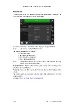
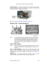
Страница 183: ...ve the outer cover of the printer to gain access to the dancing arms Do not fit a ribbon to the cassette unit for these tests When you are ready to perform the test see Procedure on page 4 32 Sensor Descriptions Note With the exception of the cassette engagement sensor all other sensor values displayed are analogue based on detection of a magnet Arm 1 4 Left and Right The arm sensor monitors the p...

Страница 184: ...ivate the sensor place a magnet in front of the sensor and verify that the sensor is activated Home Sensor Left Middle and Right This detects the position of the print head carrier See Home Sensors on page 4 33 User Interface Menu To access the menu that assists in testing the printer select Settings IO Port Monitor The following screen will display Scroll down to view the second screen ...

Страница 185: ...is in the topmost position Arm Sensors Remove the cover to gain access to the dancing arms with the cassette inserted and the power switched on Open the cassette handle by pulling it out but do not remove the cassette assembly this will prevent the ribbon motors interfering with the tests being conducted Physically move one dancing arm at a time and observe the readings on the screen The ribbon al...

Страница 186: ... sensor photocell and observe indication Cassette Handle Status LED Home Sensors To test the home sensor remove the cassette Move the print head carrier sledge slowly and gently from one side to the other while observing the sensor readings on the screen Print Head assembly Sledge See Home Sensor Left Middle and Right on page 4 31 ...

Страница 187: ...SERVICE AND FAULT FINDING 25364 Issue 8 March 2018 4 37 IO Test Select Settings IO Port Test The following screen appears Select Test Mode to check the input output settings to ensure that they are wired correctly ...

Страница 188: ... the cassette handle Printer Status LED Colour Idle Blue Ready Green Printer Open Red Printing Green Ribbon Tensioning Blue Zero Adjust Blue Park Blue Error Red Busy Yellow Initialising Red Retraction Green Speed too Low Yellow Undefined Status Yellow Returning Green Heating Print Head Blue Waiting for Prompt Input Blue Note For the specific printer state refer to the Status Bar at the top of the ...

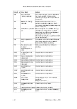
Страница 189: ...at the controller is set up to the correct printer model Verify that the motor can move the print head carrier Use the diagnostic function to check the home sensor 3 Open while printing The cassette has been opened during a printing operation 4 LVDS data not ready LVDS is the system used to send print information from the controller to the print unit A poorly grounded cable may cause this error es...

Страница 190: ... to Global Print Settings Quality and set the print speed in the range of 50 to 400 mm s 12 Y offset too short The Y offset is too short Some parts of the print out may be missed Increase the Y offset or reduce speed 13 Ribbon Alarm The dancing arm has reached the top of its travel usually because the ribbon is broken or there is no more ribbon left Check remaining ribbon In some scenarios an exce...

Страница 191: ...icator II only Power loss or damaged power supply 30 24V Low for Compact 32d 32c and 53c only Power loss or damaged power supply 102 Start when printer not ready The printer has received a start signal while printing Reduce speed or increase distance between start signals 103 No acknowledge on start pulse Communication error between controller and print unit Check settings and try again 104 Step c...

Страница 192: ...as too high Slow down the web speed or increase the ribbon economy 113 Washdown cover inserted Communicator II only Remove washdown cover before printing 1001 User program not started Contact service technician 1002 Step user program not started Contact service technician 1003 Step status undefined Contact service technician 1004 Step programming cancelled Contact service technician 1005 Main FPGA...

Страница 193: ...tween the print head and substrate for both CM and IM Adjust the print head by selecting Settings Production Line Setup Print Head Print Head Height 1019 Calibration required Compact 32d 32c and 53c CAUTIONS 1 When calibrating the print head must be able to extend fully ensure enough space is allowed to perform this function In CM the print head position parameter must be set to allow this in IM t...

Страница 194: ...served 1044 Design Delete Timeout Reserved 1045 Label Size Too Big The label is too large Edit the design and reduce the label size 1046 No Text Defined Yet Reserved 1047 Upgrade Failed Upgrade failed Check the Software Versions screen 1048 Special Action Not Found Error in firmware software Contact supplier and supply information on how the error occurred 1049 CRC Error All files on the controlle...

Страница 195: ...ailed Verify that the printer is correctly mounted and the print head is not obstructed 1059 Unsupported feature Will continue to print but without the unsupported feature that is being disputed 1060 File not found A file is not found Check the filename 1061 No external flash detected Some operations require an external flash card No external flash card is detected Abort the operation If required ...

Страница 196: ... log is located on the LAN check access rights 1077 Unable to create log sub dir The log sub dir could not be created If the log is located on the LAN check access rights 1078 Unable to access Network log file The network file could not be accessed If the log is located on the LAN check access rights 1079 Recursive log write log disabled Error in firmware Contact supplier and supply information on...

Страница 197: ... on another variable that in turn depends on the first variable None of the variables can thus be evaluated Check the variables dependencies 1101 Out of range The value typed in at the prompt is out of the range specified in the variable Type in a number within the range or modify the design to accept another range 1102 Invalid Value The typed in value could not be interpreted 1103 Too many charac...

Страница 198: ... statement can be like this Destination variable Source Variable A source variable in a macro can be d0 to d19 integer values f0 to f19 floating point values s0 to s19 string values Optionally Name of another variable 1112 Expected A was expected during the syntax check of the macro 1113 Illegal compare A variable is compared to another variable using an unrecognised compare operator Use one of th...

Страница 199: ...gic XOR Modulo 1123 then Expected A then was expected during the syntax check of the macro 1124 Illegal operator for strings Operator does not support strings 1125 Illegal operator for float An operator was used that does not support floating point values 1126 Illegal compare for strings Use single or double equal or to test if two strings are equal Use exclamation mark equal to test if two string...

Страница 200: ... Unknown System Var A reference is made to a system variable using the Variable Name syntax Check the name 1134 Macro Value Overwritten Not used 1135 Variable index out of range A local variable is indexed out of range Range is from 0 to 19 i e d0 d19 1136 Label not found The label referred to by a goto statement was not found Check syntax 1137 String Value overflow The maximum length of a string ...

Страница 201: ...rs 1145 Parentheses Ensure that placement of parentheses in the macro is correct 1146 Item description not found Ensure that the Item Descriptions used in the macro refer to an actual element in the design 1148 Redefinition User is trying to redefine a variable Please verify variable naming 1149 Macro out expected A variable of type Macro output was expected as destination Check syntax and destina...

Страница 202: ...und The database requested was not found by the ODBC server Check ODBC server 1182 ODBC Database not prepared The ODBC server needs to prepare the database Check ODBC server 1183 ODBC Unknown error Unknown error 1184 ODBC table or column not found The table or column was not found Check database and input data 1185 ODBC error while executing sql The ODBC server failed while executing an SQL statem...

Страница 203: ...untered in the printing process that has halted the print Check the preceding errors 1227 Error Reading Design Field s could not be read Design could be damaged Check design 1228 Unknown error while reading design Design could be damaged Check design 1229 Unable to print System log failed On a 21 CFR Part 11 compliant system printing cannot start if the system log fails Check free space 1230 Inval...

Страница 204: ...work shortcut Consult the network administrator 1262 Already connected to network The network thinks connection has already been made 1263 Shortcut name is invalid The name of the network shortcut is invalid Please check the name 1264 1265 Network path not acceptable invalid or cannot be located Problem with the network path A network path syntax is ServerName ShareName 1266 Network busy Try later...

Страница 205: ...ork error occurred General network error 1284 Network connection Timeout The network connection timed out Try again 1290 Invalid IP Address Check the IP address 1291 IP Conflict Check the IP address or use DHCP 1292 Unable to register host name Check the host name 1293 Disconnection Failed Try again 1294 Error Disable Network Thread Switch off unit 1400 Windows Socket Init Failed Could not initial...

Страница 206: ... 1412 Error Reading String A string was supposedly sent but the receiver could not recognise the format Check transmission Lower the baud rate Enable Hardware handshake 1413 Error Reading Integer An integer was supposedly sent but the receiver could not recognise the format Check transmission Lower the baud rate Enable Hardware handshake 1414 Error Reading Double A floating point number was suppos...

Страница 207: ... use Try later 1426 Invalid host address No unit with the specified name or address could be found Check name and network connection 1427 Unable to create new socket Try again Reboot unit 1428 Unable to connect socket Try again Reboot unit 1429 The socket is not connected Try again Reboot unit 1430 Invalid socket package Try again Reboot unit 1431 Unable to start listen thread Reboot unit 1432 Err...

Страница 208: ...ception of data to a serial variable with a specific input definition Check the serial variable and the data sent by the external device 1444 Error starting Human readable network socket Try using the standard port 9100 or another available port 1500 Not enough memory The printer is out of memory Printer needs to be rebooted 1602 More that one upgrade found You have more than one file named upgrad...

Страница 209: ...rades not supported Non CFR21 part 11 upgrade needed 1617 Incorrect platform The software in the unit did not meet the requirements for the upgrade Check which version is installed and which version is required by the upgrade file 1618 Unsupported version The software in the unit did not meet the requirements for the upgrade Check which version is installed and which version is required by the upg...

Страница 210: ... Error detected at slave printer See Printer Slaves on page 2 38 If required go to the slave printer to amend any issues 1651 Slave printer has active slaves One of the slave printers is already set up to be a master Either remove the slave printer from the list or ensure that the slave does not have any slaves of its own 1652 Slave list contains this printer One of the slave printers has the mast...

Страница 211: ... Is there adequate air pressure normally set to approximately 2 5 3 5 bar Is the print head gap even along its length compared to the substrate Is the print head parallel to the print roller Is the print head set to Top Dead Centre on the print roller Bear in mind the printer may operate slightly better 1 2mm before or after TDC Is the print head set at the correct optimum angle Is the print head ...

Страница 212: ...at Ribbon Economy is initially set to 4 Check that Retraction Offset is set to 1mm Check that Retraction Offset is set to 1mm Check that Y Offset is set to 1 2mm Check that Y Offset is set to 30mm dependent upon speed Check that Head down is set to 30ms Check that Head down is set to 40ms dependent upon speed Check that Head up is set to 15ms Check that Head up is set to 15ms dependent upon speed ...

Страница 213: ...eater being used and set appropriately that is 30 for cold environments Is the peel off roller in the correct position parallel to head and clean Is the print design correctly made and stored Setting Condition Applicable to IM Setting Condition Applicable to CM Setting Condition to Check ...

Страница 214: ...ulty Ensure that the printer is ready to print as the print head retracts when the printer is not ready for example if no design has been selected For Communicator II only Check the air supply is at the appropriate level Poor Print Quality The most common cause of poor print quality is a dirty print head Clean the print head using Cleaning Pens P N VPR0223 Cleaning Fluid P N WJ 111 and Print Head ...

Страница 215: ...further details If lines of dots are not printing and cleaning the print head and platen roller does not resolve the problem replace the print head For Communicator II only Check the air supply is at the appropriate level Air pressure settings For Communicator II only Make sure that the air is connected on the rear of the printer body Check that the air pressure regulator is set to the required pr...

Страница 216: ...will ensure that the print head life will be used to its optimum Contrast levels that are too high may also contribute to poor print quality or ribbon breakage especially when printing barcodes or horizontal lines The maximum contrast level for any print speed is 120 Faded print Print quality is dependent on the following Quality of the substrate and ribbon being used print contrast print speed co...

Страница 217: ...t and in extreme conditions the head heater on the head can make a difference to the permeability In environments of high temperature and humidity the applied ribbon may still be warm and could rub off Use a different ribbon grade The ribbon substrate may be mismatched Some substrate has coatings that make it very difficult to adhere to The coatings may be for example a wax resin mix similar to th...

Страница 218: ...ten A damaged print roller will cause print quality problems A flat spot on the roller will appear as a repeated blank area on the Test pattern Encoder Check that the encoder is rotating freely When in CM it will not print unless the encoder is moving Check that the encoder signal is sending a signal back to the controller Ribbon Drive Problems If the print contrast is too high or the print speed ...

Страница 219: ...ed lines in the print Clean the print head using Cleaning Pens P N VPR0223 Cleaning Fluid P N WJ 111 and Print Head Cleaning Wipes P N MT25215 Perform a thorough cleaning Any scratches on the rubber platen or rubber roller affects the print Thoroughly clean the rubber platen and rubber roller If scratches remain on the platen or roller replace one or both accordingly One or more defect print dots ...

Страница 220: ... print head it is important to enter the new resistance value by going to settings selecting hardware and choosing the printer type The print head cable is incorrectly installed after changing the print head Ensure all power is off before checking this The print head is worn out Print does not stick to the material and is not resistant to soft scratching Contrast is adjusted incorrectly Incorrect ...

Страница 221: ...2c and 53c or 1000mm sec for Communicator II In CM go to Global Print Settings and tick Fast Mode Ribbon keeps breaking Upon activating ribbon economy reduce pressure The ribbon spool is damaged The contrast is too high The ribbon is not fitting correctly over the top of the print head guide roller s For Compact 32d 32c and 53c only If using 22mm wide R1 Grade ribbon the ribbon tension must be red...

Страница 222: ...l or the error signal from the printer is not connected correctly Test from the diagnostic menu on the printer The signal from the printer is incompatible with the packaging machine Display shows Printer open The printer detects whether the cover or cassette is fitted Display shows Ribbon error A sensor within the printer body checks how much of the ribbon is used If this error is displayed when t...

Страница 223: ...asyprint ribbon Sensor arm may be defective Verify the sensors using the sensor test located in the diagnostics menu Compact 32d 32c and 53c print head does not move up and down The print head motion is driven by the stepper motor Check the contacts between the side arm gear segments and the fifth stepper motor gears Check the side arm gears for damage Check that the print head up down motion is s...

Страница 224: ... the head does not drive check the following The drive belt and drive pulleys Are the stepper motor connections correct Check the condition of the linear slide With the power to the unit turned off is the print head free to move along the slide If the fault persists board replacement may be required Ensure that the printer is ready to print as the print head retracts when the printer is not ready ...

Страница 225: ...and eventually break IM only Check that the printer is printing whilst the substrate is stationary CM only Check that the energy to the print head is not too high When increasing the level of ribbon economy reduce the Print Head Pressure value setting to compensate for extra friction forces that are applied on the ribbon during printing Reducing the Print Head Pressure value reduces the friction f...

Страница 226: ...MAINTENANCE SERVICE AND FAULT FINDING 4 76 25364 Issue 8 March 2018 THIS PAGE INTENTIONALLY LEFT BLANK ...

Страница 227: ... REFERENCE CONTENTS Page COMPACT 32D 32C AND 53C SYSTEM SPECIFICATION 5 3 Compact Touchscreen 5 3 Printer Specification 5 3 Power Supply Unit 5 5 COMMUNICATOR II SYSTEM SPECIFICATION 5 6 Touchscreen 5 6 Printer Specification 5 7 PRINTING DATA 5 9 ...

Страница 228: ...TECHNICAL REFERENCE 5 2 25364 Issue 8 March 2018 THIS PAGE INTENTIONALLY LEFT BLANK ...

Страница 229: ...sories Wall brackets Operating environment 5 40 C Humidity 20 80 RH non condensing Printer Specification Printing Mode Intermittent and Continuous Left hand Right hand Both options available convertible with no extra parts in 15 minutes Print resolution 300 DPI Maximum print area IM 32mm 53mm x 55mm Maximum print area CM 32mm 53mm x 500mm Print Speed max IM 400mm s Speed Range CM 10mm s 750mm s Pr...

Страница 230: ...ot swappable Shared Compact Touchscreen via Ethernet cable or network PC based interface via Ethernet cable or network Connectivity Ethernet USB x 2 mini USB service CAUTION The ethernet socket includes Power over Ethernet output PoE Inputs Print Go Encoder Outputs Error Ready Ribbon Low Spare volt free contacts Special features Master slave password Fast Mode Label creation Onboard or via EasyDes...

Страница 231: ...ower Supply Unit Dimensions 135mm x 58mm x 35mm Weight 0 5kg Rated Input Voltage Range 90 264V 1 5A Output Voltage 24V d c Rated Output Power 120W subject to de rating Working Temperature 0 to 50 C subject to de rating Storage Temperature 20 C to 85 C ...

Страница 232: ...een Operating System Windows CE 7 Dimensions mm 307 W x 232 H x 75 D IP Rating Designed to IP55 Mounting Accessories Full range of brackets Temperature 5 45 C Humidity 10 90 non condensing Electrical supply voltage 100 230 VAC Electrical supply frequency 20W 50 60 Hz Weight 2 85 kg Mounting VESA 75 Mounting Standard Ethernet Cable 5m and 10m ...

Страница 233: ...to 5 prints per second in IM based on 2 line print Print speed CM mm sec 50 800 Normal Mode 500 1400 Fast Mode Print Density 300 DPI Character Control Real Time Clocks Text in true type fonts Logos Barcodes and Graphics Graphics Format Monochrome PCX Monochrome BMP User Interface EasyView Web browsable GUI option available Label Creation EasyDesign PC application Also compatible with Connect Codes...

Страница 234: ...tal card External SD card up to 2GB No limit for external USB Electrical supply 115v to 230V 50 60Hz Fuse 4 amp T 5x20 UL Compressed Air Inlet Min 2 bar Compressed Air Inlet Max 5 bar Compressed Air regulated 2 5 bar according to application Operating Temperature Celsius 5 to 40 Ribbon length 1600 metres up to 3500m effective length with Economy mode Approvals CE IP Rating Designed to IP44 when pr...

Страница 235: ...imSun Symbol Tahoma Times New Roman Trebuchet MS Tunga Veranda Webdings Windings The fonts MRV OCRA I MRV OCRA III MRV OCRA IV MRV OCRB I MRV OCRB III MRV OCRB IV OCR A and OCR B are distributed under a licensing agreement with Morovia Software Inc Note Additional fonts can be added as options Barcodes Aztec Codabar Code 128 Code 39 Data Matrix GS1 Data Matrix DUN 14 EAN 128 EAN 13 EAN 8 EAN Add o...

Страница 236: ...TECHNICAL REFERENCE 5 10 25364 Issue 8 March 2018 THIS PAGE INTENTIONALLY LEFT BLANK ...

Страница 237: ...25364 Issue 8 March 2018 6 1 PART 6 GLOSSARY OF TERMS CONTENTS Page GLOSSARY OF TERMS 6 3 ...

Страница 238: ...GLOSSARY OF TERMS 6 2 25364 Issue 8 March 2018 THIS PAGE INTENTIONALLY LEFT BLANK ...

Страница 239: ...rints onto the moving substrate DHCP Dynamic Host Configuration Protocol A protocol used to assign dynamic IP addresses on a dynamic network DIN Connector Type of connector that widely conforms to one of the standards defined by a German standards setting organisation DNS Domain Name System This system converts domain names into IP addresses EasyDesign Label creation message designing software pac...

Страница 240: ...ndard for accessing different database systems EasyView Common user interface that will be used across Easyprint s technologies Range Information presented by the printer the range between which the value should appear Ribbon Economy Patented feature that enables user to select how much ribbon will be used for each print If this menu is set to 0 the printer will use exactly the same area of ribbon...

Страница 241: ...rovided to enable a USB mass storage device to be inserted The device can contain information that the printer can use to restore or can be used to create back ups etc Unicode An international coding scheme for written characters and text each of which is identified by a 16 bit code between 0000 and FFFF The code conforms to a Standard maintained by the Unicode Consortium and ISO organisation VGA ...

Страница 242: ...GLOSSARY OF TERMS 6 6 25364 Issue 8 March 2018 THIS PAGE INTENTIONALLY LEFT BLANK ...

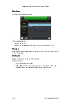
Страница 243: ...Communicator II Product Manual Easyprint A S has a policy of continuous product improvement the Company therefore reserves the right to modify the specification contained within this document without notice Easyprint A S 2018 All rights reserved For additional documentation including other available languages either scan the QR code or go to https www easy print com downloads ...

Отзывы: