EasyIO FC20 User Reference v1.3
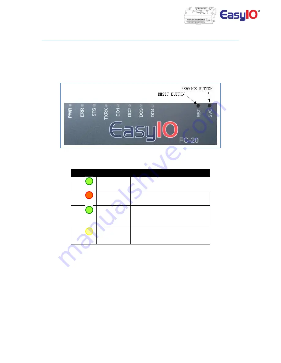
Buttons and Indications
The controller will do a hardware reset when the Reset Button is pressed whenever manual restart is
required.
The Service button is used to activate the built-in bootloader program for software upgrade.
Each digital output has a correspondence LED to indicate its current state.
Button and LED indications
LED Conditions
Description
1
PWR
PWR is used to indicate the presence of
24VAC power source, and internal power
2
ERR
ERR is to indicate whenever there is
communication errors.
3
STS
STS is used to indicate the heartbeat of the
Microcontroller. The STS LED will blink at
1-second interval in normal operation
condition.
4
TXRX
TXRX is used to indicate when there are
communication activities (Transmitting or
Receiving) on the communication port.


