


8
PREPARING TO TIG WELD
TORCH DISASSEMBLY
1.
Make sure the welder is turned off and unplugged.
2.
Remove the back cap from the torch.
3.
If there is a tungsten installed in the torch pull
it out of the front of the torch
4.
Slide the collet out of the torch.
5.
Unscrew and remove the gas nozzle.
6.
Unscrew and remove the collet body.
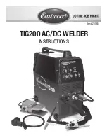
TORCH ASSEMBLY
1.
Select a collet body that matches your tungsten diameter size and thread it back into the front of the torch.
2.
Select a collet that matches your tungsten diameter size. Insert the tungsten into the collet and put the collet and tungsten back into the torch.
3.
The Gas Nozzle size should be selected according to shielding gas requirements for the material being welded.
This size can be referenced on the suggested settings chart. Select the correct gas nozzle and thread it onto the collet body.
4.
Reinstall the back cap to lock the tungsten in place. Always make sure the tungsten protrudes 1/8” to 1/4” beyond the gas nozzle.
SHARPENING THE TUNGSTEN
To avoid contamination of the Tungsten and ultimately the weld, it is imperative to have a dedicated
grinding wheel used for Tungsten grinding only. A fi ne grit standard 6” synthetic stone grinding
wheel on a bench top grinder is suffi ciene.
1.
Shut off the welder.
2.
Make sure the Tungsten and Torch are suffi ciently cooled for handling, then loosen and
remove the Back Cap then the Collet
(FIG. H)
and remove the Tungsten from the FRONT of
the Torch only (Removing from the rear will damage the Collet).
3.
If the Tungsten is used and the end is contaminated, use pliers or a suitable tool to grip the
tungsten above the contaminated section and snap off the end of the Tungsten.
4.
Holding the Tungsten tangent to the surface of the grinding wheel, rotate the Tungsten while
exerting light pressure until a suitable point is formed
(FIG. I)
.
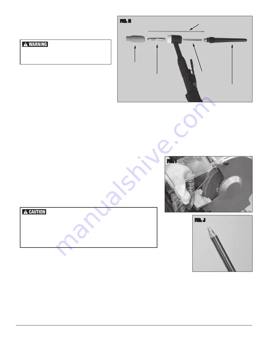
5.
The ideal tip will have the length of the conical portion of the sharpened area at 2-1/2 times the Tungsten rod diameter
(FIG. J)
.
6.
Replace the Tungsten in the Collet with the tip extending 1/8”-1/4”
beyond the Gas Nozzle, then re-tighten the Back Cap.
FIG. I
FIG. J
Gas Nozzle
Collet Body
Collet
Back Cap
Tungsten
FIG. H
✓
✓
✓
✓
✓
ELECTRIC SHOCK CAN CAUSE
INJURY OR DEATH!
Disconnect Welder from power supply before
assembly or disassembly of Torch and Cables.
FLYING METAL CHIPS CAN CAUSE INJURY!
Grinding and sanding will eject metal chips, dust, debris and sparks at high
velocity. To prevent eye injury wear approved safety glasses.
Wear an OSHA-approved respirator when grinding or sanding.
Read all manuals included with specifi c grinders, sanders or other power
tools used before and after the welding process. Be aware of all power tool
safety warnings.
Содержание TIG 200
Страница 1: ...TIG200 AC DC WELDER INSTRUCTIONS Item 20565...
Страница 14: ...14 TIG TROUBLESHOOTING...


