


7
SETUP
SHIELDING GAS CONNECTION
A Shielding Gas Bottle is not included with your Eastwood TIG 200 but is necessary while TIG
welding. A Shielding Gas Bottle can be bought at most local Welding Supply Stores. Eastwood
recommends the use of 100% Argon shielding gas when TIG welding Steel, Aluminum, and
Stainless Steel.
1.
Place the Eastwood TIG 200 in its dedicated area or on a welding cart.
2.
Secure your Shielding Gas Bottle to a stationary object or mount to your welding cart,
if it is equipped to hold one, so that the cylinder cannot fall over.
3.
Remove the cap from the Shielding Gas Bottle.
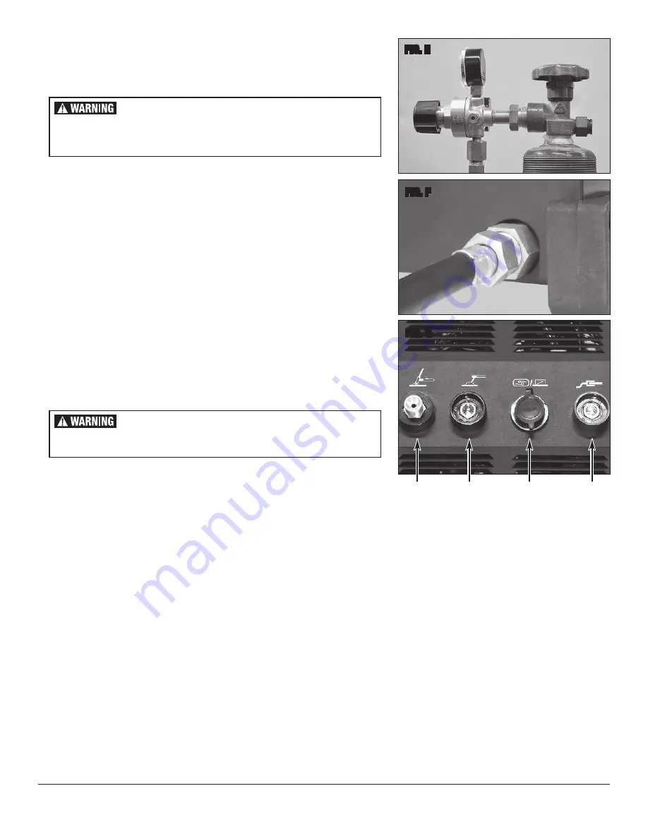
4.
Insert the large brass male fi tting on the Shielding Gas Regulator into the female fi tting on
the Shielding Gas Bottle
(FIG. E)
.
5.
Tighten the fi tting with a wrench till snug, do not over tighten.
6.
Connect either end of the Gas Line included with your Eastwood TIG 200 to the fi tting on
the regulator and tighten with a wrench until snug.
7.
Connect the other end of the gas line to the fi tting on the rear of the
Eastwood TIG 200 and tighten with a wrench until snug
(FIG. F)
.
TORCH CONNECTION
1.
Install the plastic connection cover onto the brass torch fi tting on the torch cable.
2.
Connect the female brass fi tting on the torch cable to the male brass fi tting on the
welder
(FIG. G)
.
3.
Use a wrench and tighten until snug. DO NOT OVERTIGHTEN.
4.
Connect the black 5 pin plug to the Torch Switch/Foot Pedal Connection as shown in
(FIG. G)
.
NOTE:
Omit this step if you will be using the foot pedal for Amperage control.
GROUND CABLE CONNECTION
1.
Locate the Ground Cable and Clamp.
2.
The Ground Cable connection is located at the far right of the front panel as shown in
(FIG. G)
. With the Key on the connector in the 12 O’clock position,
insert the connector and turn 180° clockwise to lock in the connector.
FOOT PEDAL CONNECTION
1.
If you are going to be using the switch on the torch to start the welding arc, omit this step.
2.
Connect the Black 5 pin plug on the Foot Pedal to the Torch Switch/Foot Pedal Connection as shown in
(FIG. G)
.
STICK WELD CONNECTION WITH OPTIONAL 20517 EASTWOOD STICK WELD TORCH.
1.
Disconnect and remove the TIG Torch/Foot Pedal Connections if in place.
2.
Insert the BLACK Stick Weld Connector into the BLACK Stick Weld Connection located at the far left of the Front Panel
(FIG. F)
. With the Key of the
Connector at the 12:00 position, push in and rotate 180° Clockwise to lock the connector in.
3.
Insert the RED Ground Connector into the RED Ground Connection located at the far right of the Front Panel
(FIG. F)
. With the Key of the Connector at the
12:00 position, push in and rotate 180° Clockwise to lock the connector in.
NOTE:
The above connections are the standard default for Stick Welding.
If your material or rod preference dictates it, the Stick Weld and Ground Connections may safely be reversed.
FIG. E
FIG. F
FIG. G
Ground
Cable
TIG
Torch
Switch/Foot
Pedal
Stick
Torch
Gas Flow
Through
Power
Cable
✓
✓
✓
✓
BUILDUP OF GAS CAN INJURE OR KILL!
Shut off shielding gas supply when not in use.
Ensure adequate ventilation. Do not weld in confi ned spaces.
Always turn your face away from valve outlet when opening cylinder valve.
ELECTRIC SHOCK CAN CAUSE INJURY OR DEATH!
Disconnect Welder from power supply before assembly or disassembly
of Torch and Cables.
Содержание TIG 200
Страница 1: ...TIG200 AC DC WELDER INSTRUCTIONS Item 20565...
Страница 14: ...14 TIG TROUBLESHOOTING...


