background image

8

PREPARING TO wELD

TORCH DISASSEMBLY/ASSEMBLY
DISASSEMBLY:

1. Make sure the welder is turned off and unplugged.
2. Remove the back cap from the torch.
3. If there is a tungsten installed in the torch pull

it out of the front of the torch

4. Slide the collet out of the torch.
5. Unscrew and remove the gas nozzle.
6. Unscrew and remove the collet body.

ASSEMBLY:

1. Select a collet body that matches your tungsten diameter size and thread it back into the front of the torch.
2. Select a collet that matches your tungsten diameter size. Insert the tungsten into the collet and put the collet and tungsten back

into the torch.

3. The cup size should be changed according to shielding gas requirements for the material being welded. This size can be referenced

on the suggested settings chart. Select the correct gas nozzle and thread it onto the collet body.

4. Reinstall the back cap to lock the tungsten in place. Always make sure the tungsten protrudes 1/8” to 1/4” beyond the gas nozzle.

SHARPENING THE TUNGSTEN

To avoid contamination of the Tungsten and ultimately the weld, it is imperative to have a dedicated grinding wheel used for 
Tungsten grinding only. A fine grit standard 6” synthetic stone grinding wheel on a bench top grinder is sufficient or specifically 
designed Tungsten Grinders are available.

1. Shut off the welder.
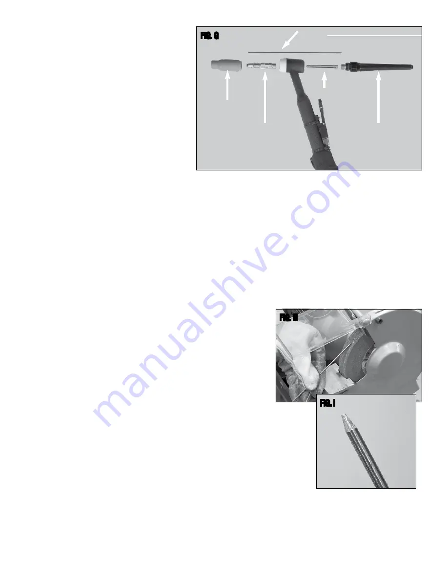
2. Make sure the Tungsten and Torch are sufficiently cooled for handling then

loosen and remove the Back Cap then the Collet (Fig G) and remove the

Tungsten from the FRONT of the Torch only. (Removing from the rear will

damage the Collet).

3. If the tungsten is used and the end is contaminated, use pliers or a suitable

tool to grip the tungsten above the contaminated section and snap off the end

of the Tungsten.

4. Holding the Tungsten tangent to the surface of the grinding wheel, rotate the

tungsten while exerting light pressure until a suitable point is formed (Fig H).

5. The ideal tip will have the length of the conical portion of the sharpened area at

2-1/2 times the Tungsten rod diameter (Fig I).

6. Replace the Tungsten in the Collet with the tip extending 1/8”-1/4”

beyond the Gas Cup, then re-tighten the Back Cap.

FIG. H

FIG. I

Gas Nozzle

✑✒✓✔

Collet Body

✑✒✓✔

Collet

✑✒✓✔

Back Cap

✑✒✓✔

✑✒✓✔

Tungsten

FIG. G

Содержание TIG 200 DC WELDER

Страница 1: ...TIG200 DC WELDER ASSEMBLY OPERATING INstructions Part 14100...

Страница 2: ...RECTING THE DEFECT OF THE EASTWOOD PRODUCT EASTWOOD WILL NOT BE LIABLE FOR INCIDENTAL OR CONSEQUENTIAL DAMAGES SUCH AS LOSS OF BUSINESS ETC CAUSED BY THE DEFECT OR THE TIME INVOLVED TO CORRECT THE DEF...

Страница 3: ...ound condition with no damage or frays and of the correct wire gauge 220 Volt 10 gauge minimum 110 Volts 12 gauge minimum Keep all cords as far away from the welder unit as possible to avoid any possi...

Страница 4: ...and skin protection Always weld with a helmet that covers your entire face and neck Always use a helmet with a lens of Shade 10 or darker Always cover all bare skin with protective clothing Flame ret...

Страница 5: ...ntaining 100 Argon must be used when TIG welding and is available at any welding supply facility Dedicated stainless steel wire welding brushes for each material to be welded A dedicated fine grit syn...

Страница 6: ...to the Panel Control position the Torch Trigger is activated Fig A 6 Torch Switch The switch on the torch Fig C controls starting and stopping the arc When using the torch switch the Amperage is set...

Страница 7: ...ncluded with your Eastwood TIG200 DC to the fitting on the regulator and tighten with a wrench until snug 7 Connect the other end of the gas line to the fitting on the rear of the Eastwood TIG200 DC a...

Страница 8: ...o avoid contamination of the Tungsten and ultimately the weld it is imperative to have a dedicated grinding wheel used for Tungsten grinding only A fine grit standard 6 synthetic stone grinding wheel...

Страница 9: ...te value with the Knob located at the left side of the regulator Shielding Gas Flow Adjustment After connecting your Shielding Gas Regulator the gas flow rate needs to be adjusted so that the proper a...

Страница 10: ...or flap disc to clean the areas to be welded Do not use the brush or flap disc for any other purpose 6 Making sure all your safety gear is in place Welding Mask Welding Gloves non flammable long sleev...

Страница 11: ...rrect arc length Make sure the tungsten is held 1 8 to 1 4 inch off the work piece Incomplete circuit Check Ground connection Make sure that the ground is on a freshly cleaned surface and close to the...

Страница 12: ...12 TROUBLESHOOTING 1 2 544 0 507 506 84 1 2...

Страница 13: ...2 4mm 3 32 12822 TIG200 Collet 1 6mm 1 16 12824 TIG200 Collet 2 4mm 3 32 12825 TIG200 Long Back Cap 12819 TIG200 Gas Nozzle 9 8mm 3 8 12821 TIG200 Gas Nozzle 11 2mm 1 2 13953 TIG Accessory Kit OTHER W...

Отзывы: