background image

10


Eastwood Technical Assistance: 800.343.9353  >>  [email protected]

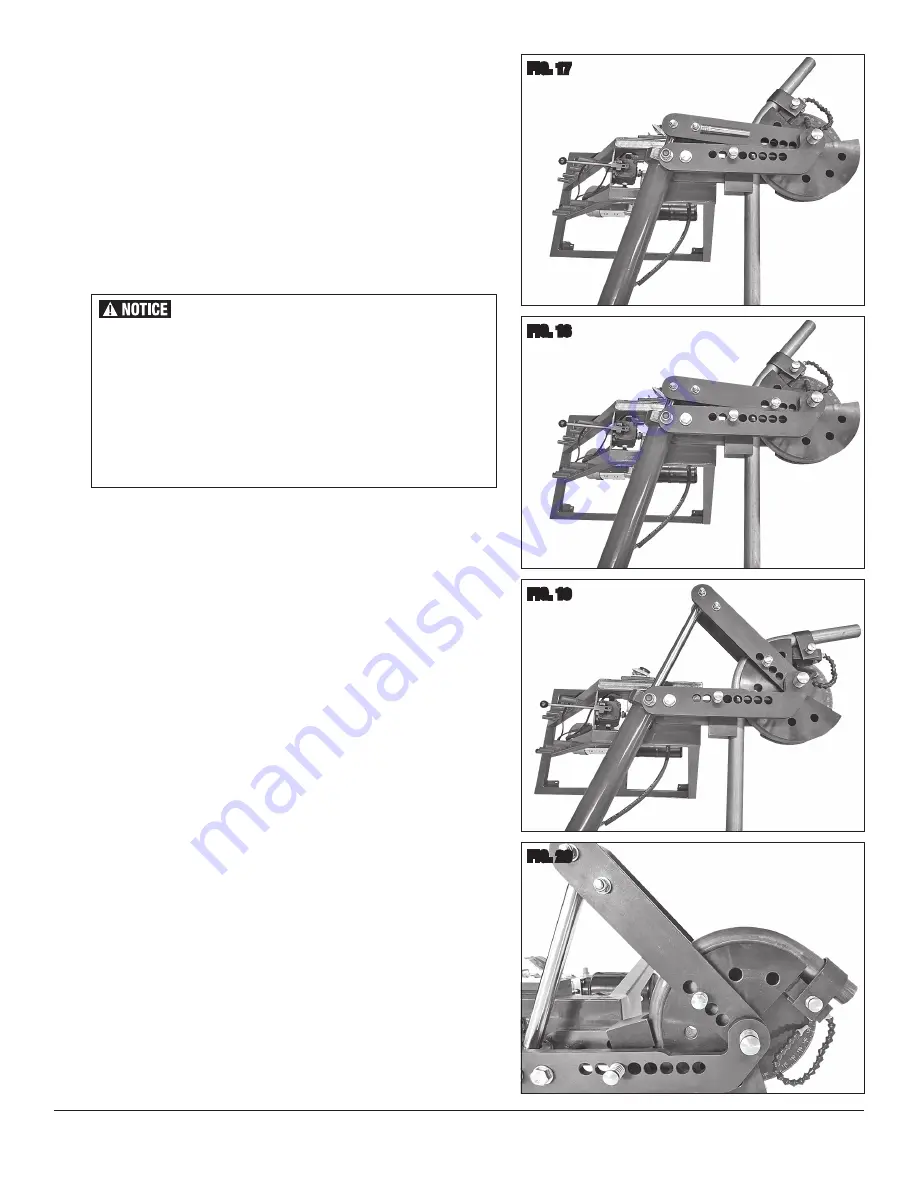
FIG. 17

At the end of the stroke, the Die Drive Pin 

[K]

 must be pulled out and repositioned in the 

Drive Arms closer toward the center of the Die as follows:  

•  Very lightly, modulate the Actuating Handle upward to retract the Cylinder slightly 

to relieve any tension in the workpiece and Die components.

•  Pull the Die Drive Pin 

[K]

 from the Die and Die Drive Arms 

(FIG 17)

 and fully 

retract the Cylinder by moving the Actuator Handle upward.

•  Move the Die Drive Pin 

[K]

 to another hole further inward on the Die 

(FIG 18)

.  

NOTE:

 If the pin holes in the Die Drive Arms do not align with the next available 

Die hole, the Cylinder may be advanced slightly to allow Pin alignment.

•  As previously, slowly and steadily push downward on the Bender Handle, continu-

ing to further bend the workpiece tubing. Watch the position of the Pointer on the 
Degree Wheel carefully as the desired bend angle is approached

 (FIG 19)

•  To achieve more bending range as needed; the above steps may need to be 

repeated until the desired bend angle is reached 

(FIG 20)

.


There will be a certain amount of “springback” meaning that the 
Pointer must be pushed several degrees past the Degree Wheel 
target then allow it to “spring back” to the final degree mark. 
This varies widely according to the particular material, diameter 
and thickness. Chromoly and high carbon steel will generally 
have more “springback” than milder steels and aluminum. This 
is one reason that some “trial and error” must be performed to 
explore the properties of the material before working on a final 
project piece.

FIG. 18

FIG. 19

FIG. 20

Содержание HYDRAULIC TUBING BENDER

Страница 1: ...HYDRAULIC TUBING BENDER INSTRUCTIONS Item 22199 Tubing Bender Dies sold separately...

Страница 2: ...F 1 Flexible Pointer G 1 2 Long x 7 8 U Strap Pin H 1 3 Long x 7 8 U Strap Pin J 1 4 25 Long x 7 8 Die Drive Pin K 1 5 35 Long x 7 8 Follow Block Pin L 1 5 5 Long x 1 Pivot Pin M installed 2 30mm I D...

Страница 3: ...oided could result in minor or moderate injury NOTICE is used to address practices not related to personal injury SAFETY INFORMATION The following explanations are displayed in this manual on the labe...

Страница 4: ...n invites accidents d Remove any adjusting key or wrench before turning the power tool on A wrench or a key left attached to a rotating part of the power tool may result in personal injury e Do not ov...

Страница 5: ...w for safe handling of various lengths of tubing Excessive resistance while operating could indicate a defect with the workpiece material or broken or damaged Tubing Bender components To avoid injury...

Страница 6: ...il Reservoir FIG 4 4 Check oil level by observing the line on the Dipstick The oil level is 100 full when it is at the line 5 If oil is not present on the Dipstick a quality 10W Hydraulic Oil not incl...

Страница 7: ...Set the corresponding sized Die Follow Bar included with Die Set between the upper and lower fixed and moveable arms then add the 5 35 Long x 7 8 Fol low Block Pin L in the appropriate holes in the Fi...

Страница 8: ...r damage to the Bender occurs DO NOT USE until proper repairs are made The Eastwood Hydraulic Tubing Bender was specifically designed to be operated by one person only Never have one person operate th...

Страница 9: ...e and avoid creating possible dents or damage Begin exerting carefully modulated downward pressure on the Actuator Handle to take up any lash and eliminate looseness then set the Pointer to indicate 0...

Страница 10: ...w Pin alignment As previously slowly and steadily push downward on the Bender Handle continu ing to further bend the workpiece tubing Watch the position of the Pointer on the Degree Wheel carefully as...

Страница 11: ...following figures are representative of the average linear amount of tubing required for a given size and the bend radius it will yield 90 for 120 Dies and 180 for 240 Dies Please note the final tubi...

Страница 12: ...Hydraulic Pump Motor Check 120 VAC input plug connection Check for tripped circuit breaker The Pump Motor operates on a 15 Amp Minimum circuit Motor Runs Too Slow Develops Low Power Excessive voltage...

Отзывы: