166119
8/31/2006
21
To configure this example, the operator would set channels 1, 2, 5, 7, 8, 12, and 15 to seek
backup, while channels 4, 11, and 13 would be fixed. Again, the setting of high or low priority
does not matter since no channels will be bumped.
2.3.3.1 Failover Rate Options
As an alternative to dropping some channels in the above example, channel rates on the
backup link may be selectively lowered to fit in the available bandwidth. Synchronous
terminal equipment in some cases may operate effectively with reduced throughput or
response time by lowering the channel port clock rate. By utilizing this option, one or more
ports may be maintained in service after a primary link failure that would otherwise need to be
dropped.
2.3.3.2 Restoral Options
When the primary link becomes operational after a failure and switchover, the system is
designed to follow configuration settings on a per-channel basis to determine when each
channel is restored to the primary link. Most of these settings are in terms of a time delay
from when a failed primary link, Link A in this example, becomes operation (defined by a
SYNC condition).
The longer the time delay, the longer the continuous in-service period must be before the
channel is switched back to the home link. It is important to note that the timer is reset when
the link is declared failed and then restarts when the link is returned to service.
For the above example, using a “Manual” setting of the restoral timer for all channels results
in the channels remaining in the backup state even after the primary link is returned to
service. Without operator intervention, all channel circuits on the backup link would continue
operating until a backup link failure occurs. If the primary link is in service, the channels
would automatically switch back to their home link.
2.3.4 Backup with Prioritized Channels
In many cases, the most efficient balance between fault-tolerance and bandwidth utilization
results from using all the flexibility provided in the dual-composite multiplexer system.
However, it should be said that the tradeoffs to obtain good utilization of composite and
channel bandwidth, before and after link failures, may require considerable planning, as the
following examples will demonstrate.
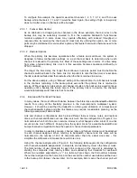
Link and channel configurations which place different failover modes, rates, and restoral
times on channels distributed over two links look much like the configuration of Figure 8 in a
normal state when both links are in service. However, what happens when a loss of one link
occurs can be much different. Knowing how the system scans for available bandwidth and
bumps channels is important to help the operator choose channel parameters.
In order to illustrate a possible scenario, channel rates and failover modes must be attached
to each channel assigned. When referring to bandwidth, channel and link rates will be
normalized to the number of 400 Hz timeslots rather than the actual clock rate – this
simplifies the arithmetic and makes the result more clear.
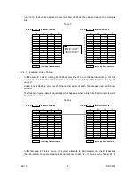
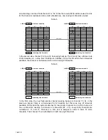
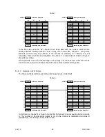
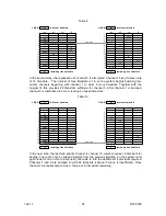
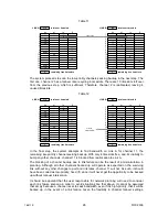
Using the channel assignments of Figure 8, the following table augments the configuration
with channel bandwidth assignments, in timeslots, and denotes by column the failover mode.
The total number of user timeslots for each link is shown at the top and is calculated by
dividing the composite clock rate by 400Hz and subtracting four timeslots for overhead.
Where two numbers separated by a “/” in a table cell are shown, the first number indicates
the number assigned on the home link, and the second the number used when switched over
to the backup link (failover channel rate). So for example, 64/4 means the channel port will
Содержание Nx8- Dual Composite MUX High-Speed 16-Port TDM Multiplexer
Страница 2: ......
Страница 6: ...166119 8 31 2006 2...
Страница 32: ...166119 8 31 2006 28...
Страница 38: ...166119 8 31 2006 34...
Страница 61: ...166119 8 31 2006 57...
Страница 62: ...166119 8 31 2006 58...


