EAS Electric Gama CND Скачать руководство пользователя страница 46

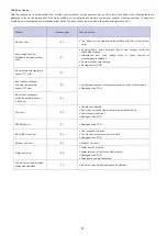
12. Air Conditioner Operations and Performance

The operating temperature range under which the unit runs stably are given in 

below table.

Do not set 

the temperature 

too low

Caution

•  The unit performs stably in the temperature range given in above table. 

If the indoor temperature is outside the unit's normal operating range, it 

may stop running and display an error code.

To ensure the desired temperature is achieved efficiently, ensure that:

•  All windows and door are closed.
•  The airflow direction is adjusted to work in running mode.
•  The air filter is clean.

Please note how you can best save energy and achieve the best 

cooling/heating effect.

Regularly clean air filters inside indoor units.

Avoid too much outdoor air coming into air-conditioned spaces.

Close doors and windows.

Check 

regularly

Note that outlet air is cooler or heater than set room temperature. Avoid 

direct exposure to outlet air as it may be too cool or hot.

Maintain a proper air distribution. Air outlet louvers should be used to adjust 

the direction of outlet airflow, as doing so might ensure more efficient 

operation.

•  During heating operation, horizontal airflow will aggravate the 

uneven distribution of room temperature.

•  The  louver  direction:  horizontal  airflow  is  recommended 

during cooling operation. Note the downward air flow will 
cause condensation on the air outlet and louver surface.

Caution

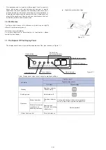
13. Adjusting Air Flow Direction

Since warmer air rises and cooler air falls, the distribution of 
warmed/cooled air around a room can be improved by positioning the 
unit's louvers. The louver angle can be adjusted by pressing the 
[SWING] button on the remote controller.

14. Maintenance

Caution

•  Before you clean the air conditioner, ensure it is powered off.
•  Check that the wiring is undamaged and connected.
•  Use a dry cloth to wipe the indoor unit and remote controller.
•  A wet cloth may be used to clean the indoor unit if it is very 

dirty.

•  Never use a damp cloth on the remote controller.
•  Do not use a chemically treated duster on the unit or leave this 

type of material on the unit to avoid damaging the finish.

•  Do  not  use  benzene,  thinner,  polishing  powder,  or  similar 

solvents for cleaning. These may cause the plastic surface to 
crack or warp.

Method for cleaning the air filter

a. The air filter can prevent the dust or other particles from 

entering the unit. If the filter is blocked, the unit will not work 
well. Clean the filter every two weeks when you use it regularly.

b.  If the air conditioner is positioned in a dusty place, clean the 

filter often.

c.  Replace the filter if it is too dusty to clean (the replaceable air 

filter is an optional fitting).

Caution

•  The control box cables originally connected to the electrical 

terminals on the main body must be removed, as indicated 
above.

1.  Dismantle the air filter(Refer to Figure 14.1).
2.  Clean the air filter

Dusts will accumulate on the filter along with the unit operation, 
and need to be removed from the filter, or the unit would not 
function effectively.

Clean the filter every two weeks when you use the unit regularly.

Clean the air filter with a vacuum cleaner or water.

a. The air intake side should face up when using a vacuum 

cleaner. (Refer to Figure 14.2)

b.  The air intake side should face down when using clean water. 

(Refer to Figure 14.3)

For excessive dusts, use a soft brush and natural detergent to 
clean it and dry in a cool place.

20


Please release pressure before disassembly.

Cooling  mode

Heating  mode

17

32

°C

(DB)

15

27

°C

(DB)

Indoor temperature

Indoor humidity

(a) Condensation will form on the unit surface  and water dripping 
out of the unit when the indoor humidity is beyond 80%

≤80%

(a)

Содержание Gama CND

Страница 1: ...2ND GEN INDOOR UNIT V 2 MANUAL DE INSTRUCCIONES INSTRUCTION MANUAL GUIDE D UTILISATION MANUAL D INSTRU ES Escanee para ver este manual en otros idiomas y actualizaciones Scan for manual in other lang...

Страница 2: ......

Страница 3: ...i n No perfore a menos que confirme la seguridad con el usuario especialmente para el cable de alimentaci n oculto Se puede usar una electroprobe para probar si pasa un cable en la ubicaci n de perfor...

Страница 4: ...de instalaci n de la unidad exterior y sus requisitos reales del proyecto Comprar seg n los requisitos del proyecto real Use para conectar la tuber a de refrigerante interior 2 Tubo de PVC para descar...

Страница 5: ...r El techo no debe presentar ning n tipo de inclinaci n Hay espacio suficiente para realizar trabajos de reparaci n y mantenimiento Sin fugas de gas inflamable La longitud de la tuber a entre las unid...

Страница 6: ...tura de la unidad interior 3 Use un nivel de burbuja para verificar que el cuerpo de la unidad est nivelado haciendo que el cuerpo de la unidad se incline hacia el lado de drenaje tal como se muestra...

Страница 7: ...orno Diagrama de la caja de control el ctrico Borde de la entrada de aire de retorno Posici n del perno de elevaci n Tama o de la salida de aire Borde de la entrada de aire de retorno Tama o de la ent...

Страница 8: ...del perno de elevaci n Conecte a una de tuber a de agua Tama o de la entrada de aire de retorno Borde de la entrada de aire de retorno Orificio de conexi n Tama o de la salida de aire Tuber a de refri...

Страница 9: ...rama de la caja de control el ctrico Entrada de aire de retorno Orificio de conexi n para el conducto de aire Salida de aire Reborde de la salida de aire Tama o de la salida de aire Posici n del perno...

Страница 10: ...t piping liquid side 28 OD 15 9 OD Positions of 4 12 25 lifting bolts 1937 1905 1940 2010 990 1600 626 316 333 680 905 905 750 500 590 316 8 Salida de aire Entrada de aire de retorno Reborde de la sal...

Страница 11: ...siguiente tabla para conocer el tama o del casquillo de la tuber a y el par de apriete adecuado Cuidado Aplique el par de apriete adecuado de acuerdo con las condiciones de instalaci n Un apriete exce...

Страница 12: ...la descarga puede producirse con un retraso de 1 minuto m s o menos y verifique si hay fu gas de agua en cada junta 5 2 2 Unidad interior con una bomba de drenaje 1 Use la tuber a de inyecci n de agu...

Страница 13: ...ones de la unidad interior se transfieran al techo 5 Utilice materiales de aislamiento t rmico con un espesor de 25 mm o m s para evitar la condensaci n en el conducto de aire 6 Conecte el conducto de...

Страница 14: ...nmutadores DIP en la placa principal para la configuraci n SW2 o el manual del mando a distancia por cable para el ajuste del mando a distancia por cable Cuatro ESP se pueden configurar a trav s del i...

Страница 15: ...Consulte las Tablas 7 1 y 7 2 para conocer las especificaciones del cable de alimentaci n y del cable de comunicaci n Un cableado con poca capacidad calentar los cables y podr ocasionar accidentes cu...

Страница 16: ...bleado de conexi n debe ser recto para que la cubierta de la caja el ctrica est nivelada y pueda cerrarse herm ticamente Use aislamiento y materiales de sellado profesionales para sellar y proteger lo...

Страница 17: ...Capacidad de refrigeraci n 0 2200W 8 10000W 0 28000W 1 2800W 9 11200W 1 33500W 2 3600W A 12500W 2 40000W 3 4500W B 14000W 3 45000W 4 5600W C 16000W 4 56000W 5 7100W D 18000W 6 8000W E 20000W 7 9000W...

Страница 18: ...cionamiento 9 1 Puntos a tener en cuenta antes de la prueba de funcionamiento 1 Las unidades interiores y exteriores est n instaladas correctamente 2 Las tuber as y el cableado son correctos 3 No hay...

Страница 19: ...ares donde pueda gotear l quido sobre la misma El agua u otros l quidos que entren en contacto con la unidad pueden provocar descargas el ctricas o incendios No retire las partes frontal o posterior d...

Страница 20: ...o Desescarche Receptor de se al infrarroja Pantalla LED digital Indicador de alarma Indicador de temporizador Indicador de funcionamiento Estado de la Unidad Visualizaci n en pantalla Paneles de visua...

Страница 21: ...o seleccione una temperatura demasiado baja 13 Mantenimiento Cuidado Antes de limpiar el equipo de aire acondicionado aseg rese de que est apagado Compruebe que el mando a distancia por cable est cone...

Страница 22: ...istema puede demorarse intencionadamente hasta 12 minutos en algunas condiciones de funcionamiento Si el LED de funcionamiento OPERATION en el panel de la unidad se ilumina el sistema funciona normalm...

Страница 23: ...eraci n Los compresores de la unidad exterior no funcionaron correctamente El voltaje de la fuente de alimentaci n es demasiado alto o demasiado bajo Hay una obstrucci n en el sistema de tuber as Bajo...

Страница 24: ...dor puede seleccionarse solo durante los modos COOL FAN ONLY y HEAT La se al del mando a distancia no se transmite incluso cuando se pulsa el bot n ON OFF Se ha producido un corte en el suministro el...

Страница 25: ...s de radiaci n electromagn tica Cable de comunicaci n demasiado largo PCB principal da ada Error del sensor de tempe ratura ambiente interior T1 E2 El sensor de temperatura no est conectado correctame...

Страница 26: ...ayor o como consecuencia de un uso anormal negligente o inadecuado del aparato 7 Responsabilidades civiles de cualquier naturaleza 8 P rdidas o da os en el software o soportes de informaci n 9 Aver as...

Страница 27: ...All wiring on site must be carried out in accordance with the connection diagram attached to the product Make sure that there are no external forces acting on the terminals and wires Improper wiring...

Страница 28: ...salt content in the air When exposed to air with a high salt content the mechanical parts will experience accelerated ageing which will severely compromise the service life of the unit 5 Where there a...

Страница 29: ...ng conditions and user requirements to install the air conditioning unit 2 2 Install with M10 or W3 8 lifting bolts 2 3 The space required for installation unit mm is shown in Figure 2 1 and Figure 2...

Страница 30: ...should be made from high quality carbon steel with galvanized surface or other rust prevention treatment or stainless steel How the ceiling should be handled will differ with the type of building For...

Страница 31: ...nnection hole Return Air Inlet Flange Return Air Inlet Flange Electric control box assembly 3 3 Dimensions 3 3 1 Installation dimensions of lifting bolts and location size of connecting piping unit mm...

Страница 32: ...erant piping liquid side Connect to water piping Position of lifting bolt Return Air Inlet Flange Return Air Inlet Flange Connection hole Electric control box assembly Return Air Inlet Air Outlet Figu...

Страница 33: ...iping liquid side Figure 3 9 7 22 OD 12 7 OD Connect to water piping Return Air Inlet Flange Air Outlet Flange Return Air Inlet Air Outlet Positions of 4 12 25 lifting bolts Electric control box assem...

Страница 34: ...Repair hole Electric control box assembly Return Air Inlet Air Outlet Refrigerant piping gas side Refrigerant piping liquid side 28 OD 15 9 OD Positions of 4 12 25 lifting bolts 1937 1905 1940 2010 9...

Страница 35: ...than the specified refrigerant do not let air or other gases enter the refrigeration circuit If the refrigerant leaks during installation make sure you fully ventilate the room Use two wrenches when...

Страница 36: ...rge piping accessory to bind them firmly to make sure air does not enter and condense 4 In order to prevent the back flow of water into the interior of the air conditioner when the operation stops the...

Страница 37: ...t exchanger which will make the air conditioner prone to failures and water leakage 3 Before installing the air duct ensure that the static pressure of the air duct is within the permitted range of th...

Страница 38: ...a 160Pa 150Pa 140Pa 130Pa 120Pa 110Pa 100Pa default 90Pa 80Pa 70Pa 60Pa 50Pa 30Pa 0 20 40 60 80 100 120 140 160 180 200 1590 1640 1690 1740 1790 1840 1890 1940 1990 2040 2090 2140 2190 2240 Static pre...

Страница 39: ...210Pa 200Pa 190Pa 180Pa 170Pa default 160Pa 150Pa 140Pa 130Pa 120Pa 110Pa 100Pa 90Pa 70Pa 60Pa 50Pa 30Pa 0 50 100 150 200 250 3720 3770 3820 3870 3920 3970 4020 4070 4120 4170 4220 4270 4320 Static p...

Страница 40: ...ntact separation The distance between the power cord and signalling line must be at least 300 mm to prevent the occurrences of electrical interference malfunction or damage to electrical components At...

Страница 41: ...er X1 X2 Indoor unit 1 Wired Controller 2 X1 X2 D1 D2 Wired Controller 1 X2 X1 D1 D2 Indoor unit 2 X1 X2 Indoor unit n n 16 D1 D2 D1 D2 D1 D2 Only the last indoor unit requires adding the build out re...

Страница 42: ...ings are completed mark the address of each indoor unit to facilitate after sales maintenance The centralized control of the indoor unit is completed on the outdoor unit For details refer to the manua...

Страница 43: ...owing items according to the manual If there is any fault troubleshoot by referring to the section Air Conditioner Errors and Causes in the manual 9 2 1 Indoor unit 1 Wired remote controller switch is...

Страница 44: ...te controller s front or back overs and do not touch the remote controller s internal components as doing so can cause injury If the remote controller stops working contact your supplier or service en...

Страница 45: ...ct type Air Outlet Air Intake Electric Control Box Figure 10 1 Figure 11 1 Infrared signal receiver Operation lamp MANUAL OPERATION TIMER DEF FAN ALARM Timer indicator Alarm indicator Check button Dig...

Страница 46: ...it is powered off Check that the wiring is undamaged and connected Use a dry cloth to wipe the indoor unit and remote controller A wet cloth may be used to clean the indoor unit if it is very dirty N...

Страница 47: ...e unit s heat exchanger coil during defrosting becomes mist and is emitted from the unit Symptom 4 Dust is emitted from the unit This can occur when the unit first runs after a long idle period Sympto...

Страница 48: ...k has occurred Low heating effect Doors or windows are not completely closed Close doors and windows Arrange for a professional technician to check the following A refrigerant leak has occurred 16 2 U...

Страница 49: ...certain time No receiving soundfrom the indoor unit when the ON OFF button is pressed Check whether the MODE indicated on the display is AUTO Check whether the MODE indicated on the display is DRY A p...

Страница 50: ...amaged main PCB Indoor EEV coil error Eb Line loosened or broken The electronic expansion valve in stuck Outdoor unit error Ed Outdoor unit error Water level error EE Water level float stuck Water lev...

Страница 51: ...eure or as a result of abnormal negligent or inappropriate use of the device 7 Civil liabilities of any nature 8 Loss or damage to software or information media 9 Faults produced by external factors s...

Страница 52: ...A Escanee para ver este manual en otros idiomas y actualizaciones Scan for manual in other languages and further updates Manuel dans d autres langues et mis jour Manual em outras l nguas e actualiza...

Отзывы: