


8.1 Capacity Settings
8. On-site Configuration
Set up the PCB DIP switch on the indoor electric control box to cater to different
uses. Once the settings are done, make sure you cut off the main power switch
again, and then switch the power on. If the power is not cut off and switched on
again, the settings will not be executed.
ENC1 Settings for Capacity DIP Switch:
Toggle
switch
Dial code
Set cooling
capacity
Cooling capacity
Toggle
switch
Set cooling
capacity
Dial code Cooling capacity
Toggle
switch
Set cooling
capacity
Dial code Cooling capacity
ENC1
POWER_S
0 1 2
F
3
E
4
D
5
C
6
B
7
A
89
+
4500W
5600W
8000W
2200W
2800W
3600W
7100W
9000W
0
1
2
3
4
5
6
7
ENC1
10000W
8
+
11200W
9
14000W
B
12500W
A
18000W
D
16000W
C
25000W
F
20000W
E
45000W
56000W
28000W
33500W
40000W
0
1
2
3
4
Reserved
Clear indoor unit address
SW3_1
SW2
External static pressure 1
External static pressure 2
External static pressure 3
External static pressure 4
Capacity
ESP1
ESP2
ESP3
ESP4
7.1-16.0kW
100Pa
50Pa
170Pa
200Pa
20.0-28.0kW
170Pa
100Pa
200Pa
250Pa
40.0-56.0kW
300Pa
100Pa
200Pa
400Pa
Note:
•
The capacity DIP switches have been configured before delivery. Only
a professional maintenance personnel should change these settings.
• Once the centralized control function for the indoor unit has been
completed on the outdoor unit, the DIP switch on main control panel of
the outdoor unit must be set to auto addressing; otherwise, the indoor
unit in the system are not controlled by the centralized controller.
8.2 Address Settings
When this indoor unit is connected to the outdoor unit, the outdoor unit
will automatically allocate the address to the indoor unit. Alternatively, you
may use the controller to manually set the address.
The addresses of any two indoor units in the same system cannot be
the same.
The network address and the indoor unit address are the same, and
does not have to be configured separately.
Once the address settings are completed, mark the address of each
indoor unit to facilitate after-sales maintenance.
The centralized control of the indoor unit is completed on the outdoor
unit. For details, refer to the manual on the outdoor unit.
Caution
Caution
• The system can connect up to 64 indoor units (address 0~63) at the
same time. Each indoor unit can only have one address DIP switch in the
system. The addresses of any two indoor units in the same system
cannot be the same. Units that have the same address may malfunction.
8.3 DIP Switch Settings on Main Board
Cooling mode temperature compensation is 0°C
Cooling mode temperature compensation is 2°C
EEV at position 96 (steps) in standby in heating mode
EEV at position 72 (steps) in standby in heating mode
SW1_1
SW1_2
16
[ ]
0
SW1
[ ]
1
SW1
[ ]
0
SW1
[ ]
1
SW1
[ ]
0
[ ]
1
SW3
SW3
[ ]
00
[ ]
01
[ ]
10
[ ]
11
SW2
SW2
SW2
SW2
Reserved
SW3_2
[ ]
0
SW3
SW7
SW7
ENC1
+
SW7
Figure 7.10
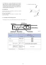
7.4 Handling the Electrical Wiring Connection Points
The X1, X2, D1, D2 ports on the sides of the main control board and the
unidirectional communication port (display board side) are for different
types of wired controllers (see Figure 7.10).
Use the connecting wires (accessory 8) to connect the D1, D2 ports.
Once the wiring and connections are done, use tie straps to secure the
wiring properly so that the connection joint cannot be pulled apart by
external force. The connection wiring must be straight out so that the
cover of the electrical box is level and can be closed tightly.
Use professional insulation and sealing materials to seal and protect the
perforated wires. Poor sealing may lead to condensation, and entry of
small animals and insects that may cause short circuits in parts of the
electrical system, causing the system to fail.
1
CN15
XS4 XP4
Main Board
CN17
Display
SW5 SW4 SW3 SW2 SW1
CN9
ENC1
SW6 SW7
To outdoor/indoor
units comm. bus
To wired
controller
comm. bus
P Q E
X1 X2
Yellow
Gray
Black
White
Blue
XT2
To wired
controller
comm. bus
D1 D2
Wired
controller
A
B
C
D
For the specific connection method, refer to the instructions in the
corresponding wired controller manual to carry out the wiring and
connections.
Caution
•
*
*
*
*
*
*
*
*
*
*
Reserved
Содержание Gama CND
Страница 2: ......